3.4.2.2. TOOLS for Revit PRO
SIGNAX Settings
The settings for the SIGNAX TOOLS plugin for Navisworks are located on the Settings panel ➤ Settings
General
License verification is performed at the beginning of using the plugin's functionality. The TOOLS module is divided into TOOLS Lite and TOOLS PRO. TOOLS Lite comes bundled with DASHBOARD and automatically picks up its authorization. TOOLS PRO is provided separately and has its authorization.
Click on the Settings panel ➤ Settings ➤ General
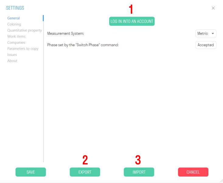 Log in with your account.
- Export plugin settings to an XML file. You can share the settings file with your colleagues so that when working with the plugin, they can use the same settings.
- Import plugin settings in XML format.
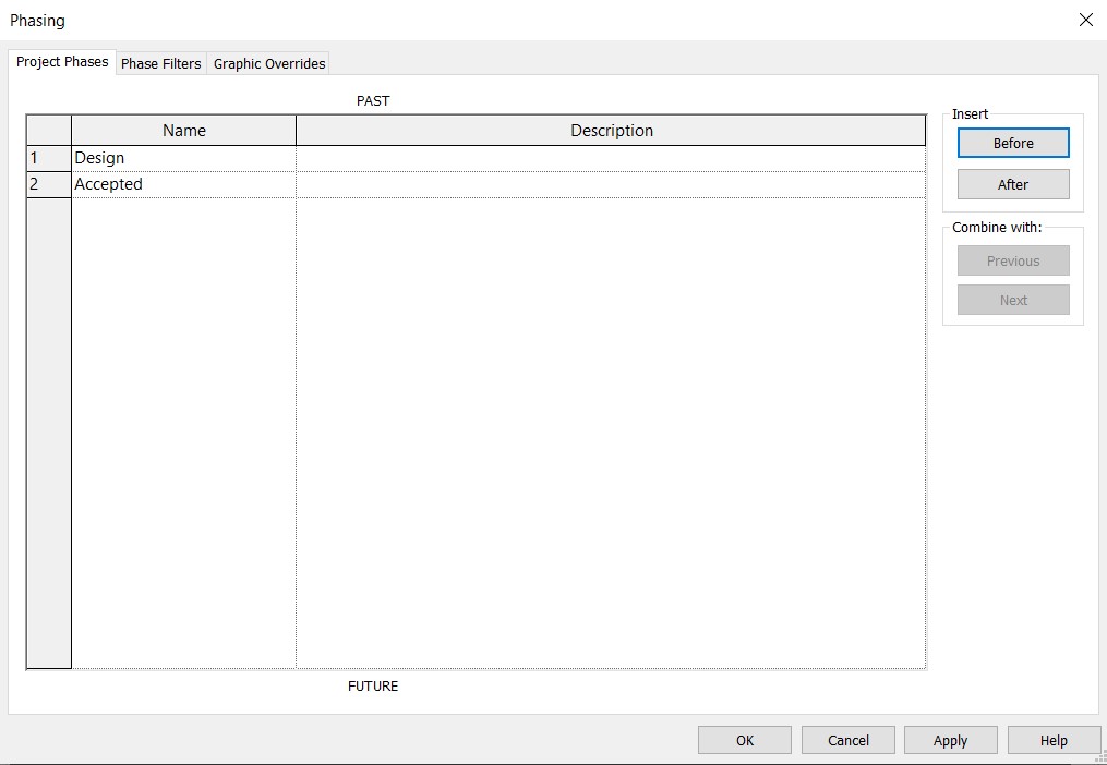
In this window, you can also choose the measurement system used in your project: Metric or Imperial. Additionally, specify the name of the stage at which the value of the "Phase Created" parameter will change when using the Change Phase tool. The default is "Accepted."
Note: The name of the stage should also be specified in Manage ➤ Phasing.
Coloring
This setting allows you to specify colors for coloring elements by creating filters for views. By using the checkbox, you can activate automatic coloring when using a command, and also assign a color for automatic assignment.
- Click on the Settings panel ➤ Settings ➤ Coloring
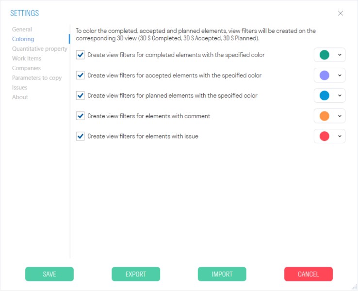
- When using the "Complete/Accept/Plan" commands, it records the value in the "S Color" parameter.
Quantitative property
In the current list, names of parameters are set for collecting cumulative numerical characteristics of elements (Volume/Area/Length) when working with the Calculations section. If an element has at least one parameter from the list, the value from that parameter is taken for calculation. The order of parameters in the list corresponds to the order of parameter search for the element.
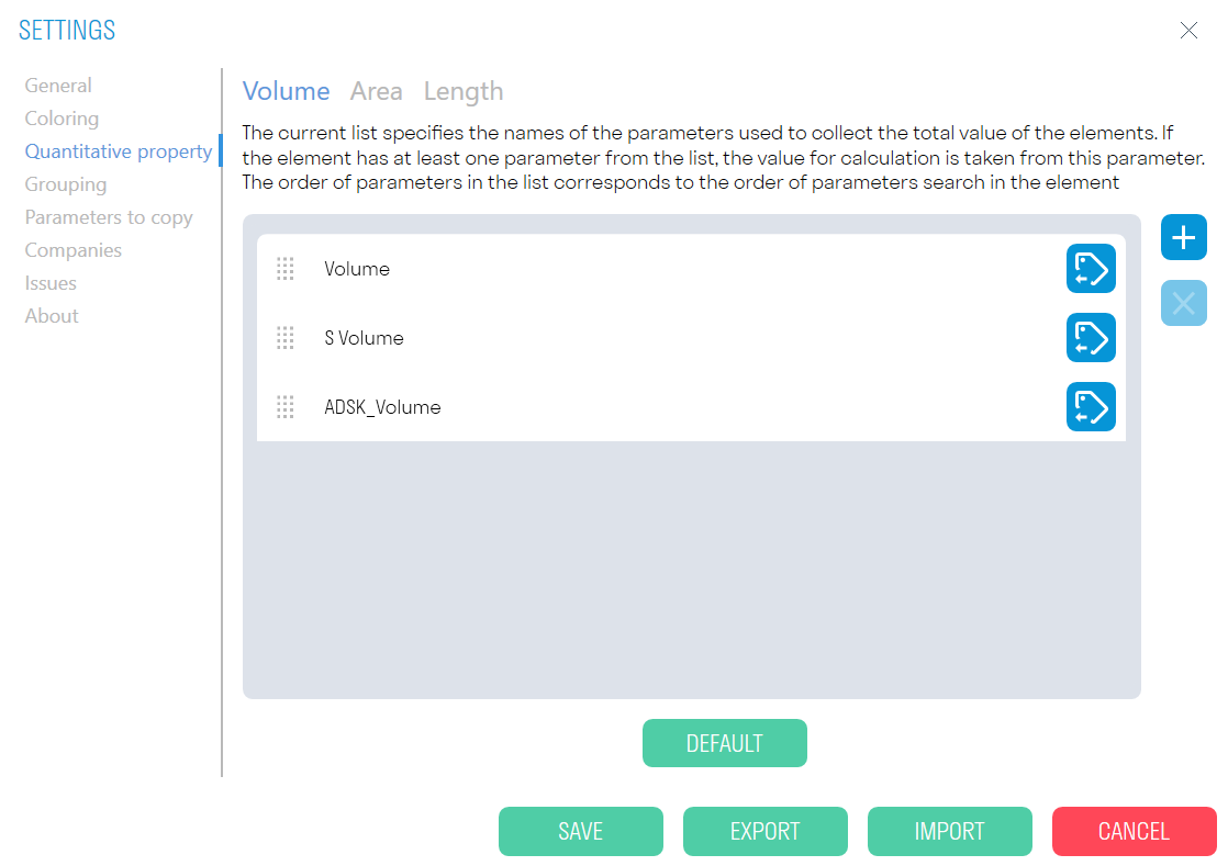
- To add a new parameter, click on the "+" sign. After that, manually enter the parameter or choose from the list.
Work items
The setup allows you to add Work items that will be specified when using the Complete/Accept/To Plan tools. Prepare your structure by types of work used on the site. Specify the Code and Name of the work, the unit of measurement, and the price per unit.
Click on the Settings panel ➤ Settings ➤ Types of Work.
You can add folders and types of work manually or import a ready-made Excel file (see the Excel table filling principle).
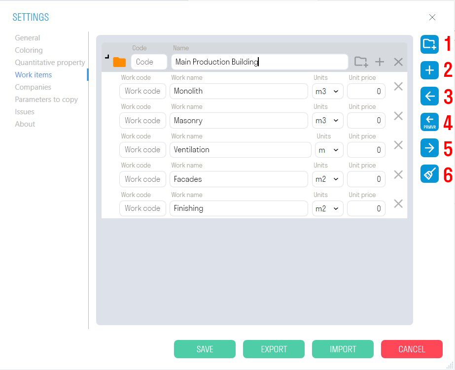
- Adding a new folder.
- Adding a new type of work.
- Importing types of work from an Excel table.
- Importing types of work from an XML file from Primavera.
- Exporting types of work to an Excel table.
- Clearing the list of types of work.
Principle of filling in the Excel table:
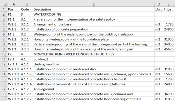
In the "Pos." column, the value is in the format F1, F1.1, F2, F2.1, F2.1.1, or W1, W1.1, W1.2, W2.1.1, where F indicates that the row defines a folder, and W creates a type of work.
1.1, 2.1, 2.1.1 - indicates the hierarchy of folders, i.e., F2.1.1 will be nested within F2.1, and the latter within F2.
W2.1.1 - means that the type of work should be created within the folder F2.1.1.
Attention! W2.1.1 may and should be repeated for all types of work placed in one folder, i.e., it does not increase with the last digit—it is not a sequential number but an indicator of the placement of the type of work.
- In the "Code" column, the work code is specified.
- In the "Description" column, the folder name or type of work is indicated.
- In the "Unit" column, the unit of measurement for the type of work is specified. For a folder, no unit of measurement is indicated.
- In the "Price" column, the price per unit of work is specified, which is used for exporting Invoice in TOOLS For Navisworks.
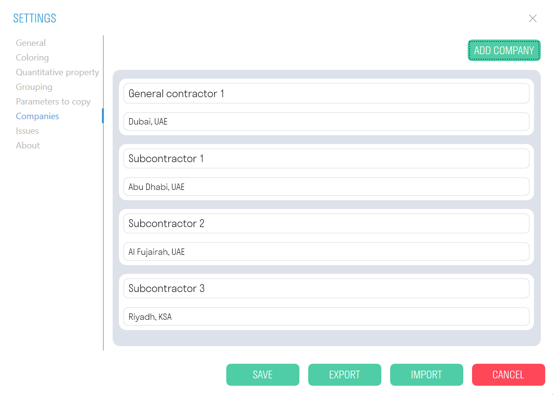
Companies
Add list of companies involved in construction project to be able to specify them using Complete/Accept/To Plan features.
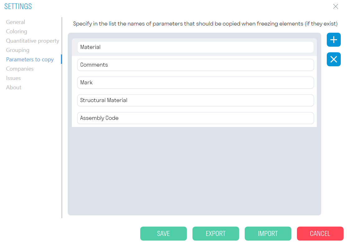
Parameters to copy
Specify parameters you would like to transfer from a linked model file using Copy elements, Copy by parameters, and Copy parameters features.
- Select Settings ➤ Parameters to Copy
- Specify the parameter name to copy "+"
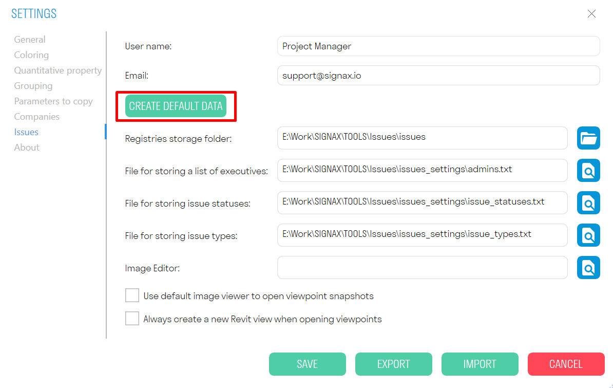
Issues
To use the BCF format Issues feature, you need to configure it in Settings. You have two options:
- Manually enter all required data - User Name, Email, Specify paths to saved .txt files with settings.
- You can also automatically "Create default data" with pre-configured .txt files. For this option, you must specify the path to the folder where the Issue settings will be stored. Later, you can edit .txt setting files and customize them based on your project requirements.
SIGNAX Features
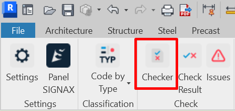
Checker
A comprehensive tool that allows you to check the model for the presence of parameters in elements and the completeness of values for these parameters. For example, before exporting the model to Navisworks, the designer can check the model for the completeness of important parameters.
Click on the Check panel ➔ Checker.
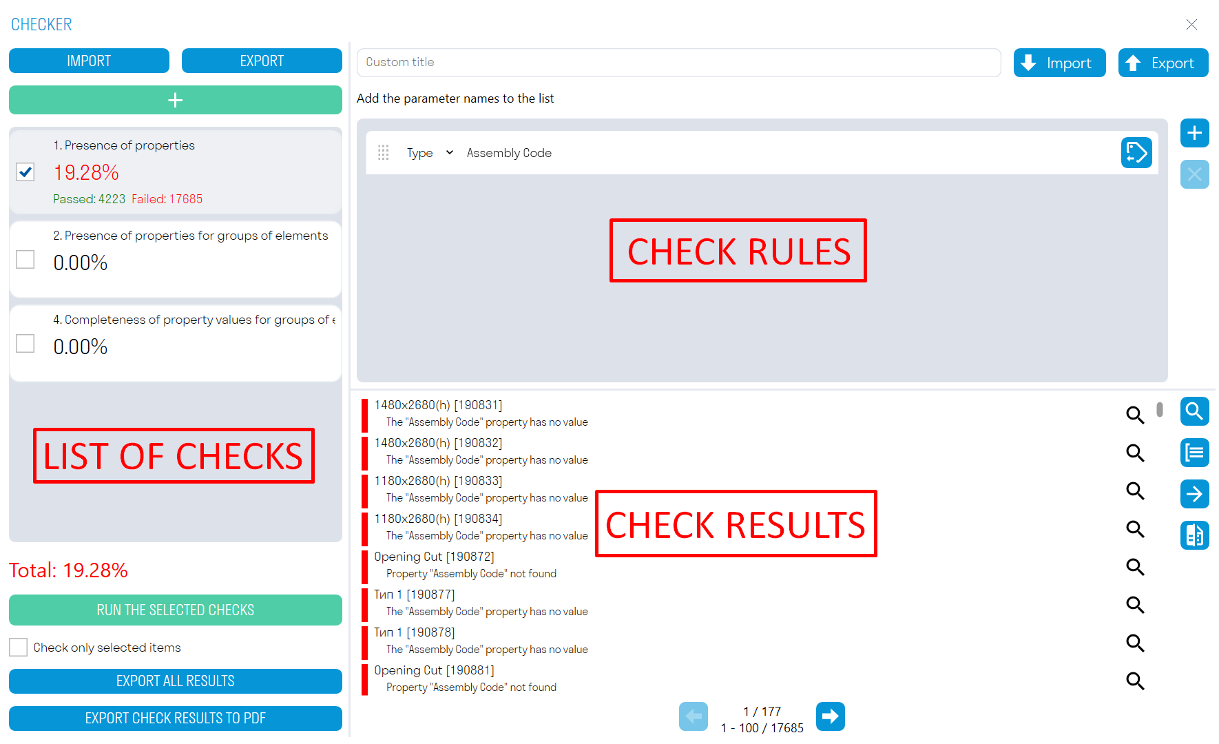
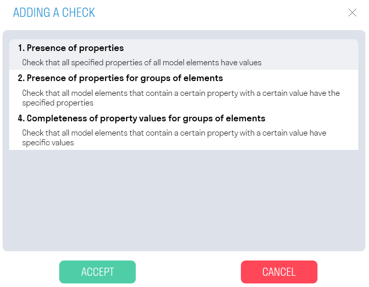
- The Checker window is divided into 3 areas: checks, rules, and results.
2. Add one of three checks by clicking 
3. Add rules and run the check by clicking "RUN SELECTED CHECKS".
4. Review elements in the model with errors, make notes, and correct errors. Export check results to Excel or XML. Compare results with previous check results to see which notes have been addressed.
Check Zone: This zone displays the percentage of completed checks and the number of elements that passed and failed the check.
- Click Add Check
 to add one of three checks.
 - EXPORT allows you to export all checks and their rules to XML. You can then send this file with checks to your colleagues.
- IMPORT allows importing an XML file with checks.
- RUN SELECTED CHECKS launches the check opposite to which there is a checkmark.
The Check only selected elements switch allows checking only the selected elements in the model. - EXPORT ALL RESULTS allows exporting the results of all checks to a single Excel file, which can be passed to colleagues to fix elements that failed the check.
Rules Zone: This zone creates rules for the check. Rules created in Navisworks are compatible with rules in Revit.
- When creating rules, it is necessary to select their type from the drop-down list - Type or Instance Parameter.
-
 button allows selecting a parameter from the list.
 -
EXPORT allows exporting check rules to an Excel file. This file can be supplemented with rules, loaded into Checker, or sent to colleagues.
-
IMPORT allows loading an Excel file with check rules. If you already have created rules in Navisworks, you can import them into Checker in Revit.
Results Zone: This zone displays the check results in the form of element names and descriptions of why the elements failed the check.
-
Click "Select All"
 to select all elements in the model that failed the check.
 -
Click
 next to the result to select one or a group of elements in the model that failed the check.
 - Click Group Results
 to group check results by repeating element names and result descriptions. Thus, the number of items in the list will decrease, making it easier to view elements that failed the check.
 -
Click Export Results
 to export check results in Excel or XML format. After fixing the issues, this XML can be compared with new results using the Compare command.
 -
Click Compare
 and load the XML file with the results of the previous check to see which notes have been addressed.


Checker - Check Types
1. Property Presence
This function checks the completeness of the check parameter value. It is suitable for checking parameters that should be filled in for all model elements.
For example, let's check that the "Assembly Code" parameter is filled in for all model elements.
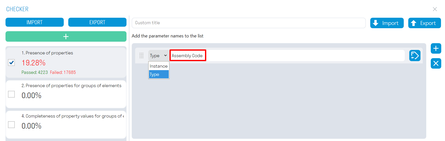
- Add a parameter by clicking +.
- Select the parameter type (Type or Instance).
- Enter the parameter Name and Assembly Code, or select the parameter from the list by clicking
 .
. - Run the check ➔ the elements that failed the check will be shown in the results zone.
 .
. 2. Properties Presence for Element Groups
Check that all model elements containing a conditional parameter with a certain value have filled check parameters. (In this context, a conditional parameter is a parameter that sets the initial condition: If the "Category" property has the value "Walls". Check parameters are checked for the presence of a filled value.)
For example, let's check that for elements with the conditional parameters "Assembly Code" "B101212," and "B101224", has parameters "Base Level" and "S Location" are filled.
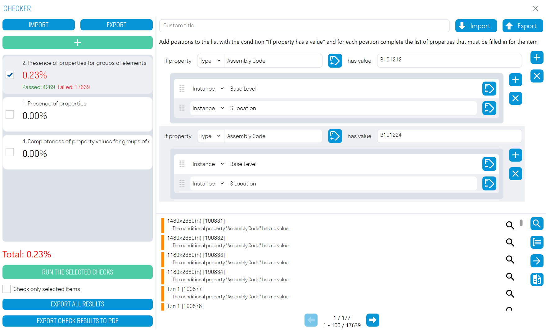
- Add a conditional parameter by selecting its type (Type or Instance) and its value.
- Add check parameters and run the check ➔ The elements that failed the check will be shown in the results zone.
It is more convenient to create rules for this check in an Excel table: all rules in Excel from Checker in Navisworks are compatible with Checker in Revit. If you already have created rules in Navisworks, you can import them into Checker in Revit or create new ones:
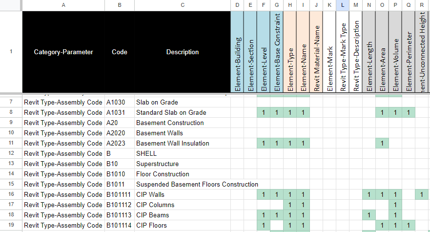
- In column A (Rule), list the conditional parameters as a pair "Parameter Type-Parameter" separated by a hyphen without spaces, and in column B (Value), specify values for these conditional parameters.
- Then, starting from row 1 in column C, list the check parameters as a pair "Parameter Type-Parameter" separated by a hyphen without spaces.
- Then fill in the cells in the matrix with any values, for example, "1", to link the check parameter to the conditional parameter.
- Thus, you get: "If the "Assembly Code" parameter has the value "A1030", then check the "Element", "Building" parameters, etc."
You can also check against other conditions, such as the Category Names.
You can download templates using the following link:
4. Completeness of Property Values for Element Groups
Check that all model elements containing a conditional parameter with a certain value have the specified value for check parameters.
For example, let's check that for elements with the conditional parameter "Category" having the value "Walls", the check parameter "Width" is equal to "250".
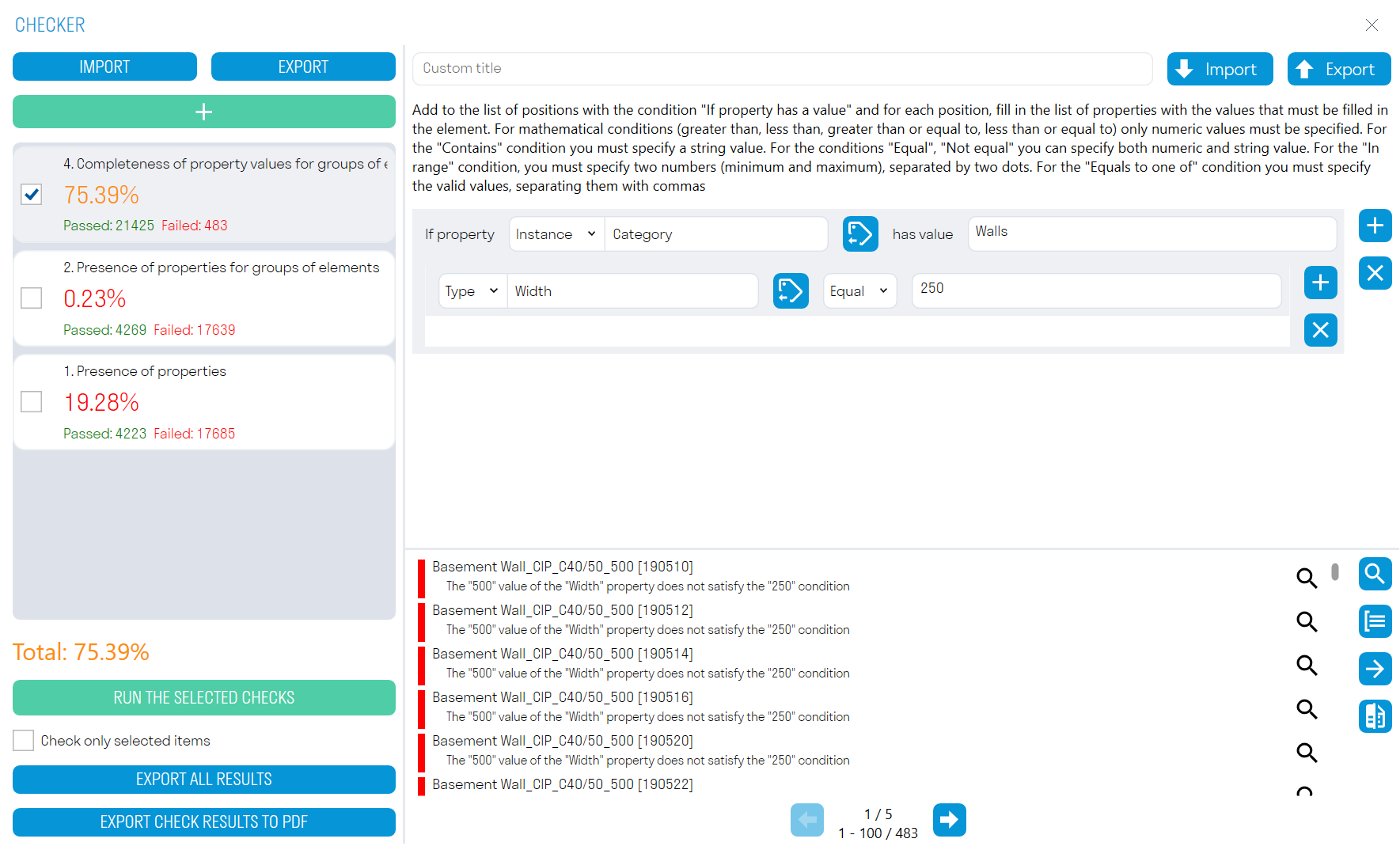
Add a conditional parameter by selecting its type (Type or Instance) and the value of this parameter. Add a check parameter and the value it should have. Run the check ➔ the elements that failed the check will be shown in the results zone.
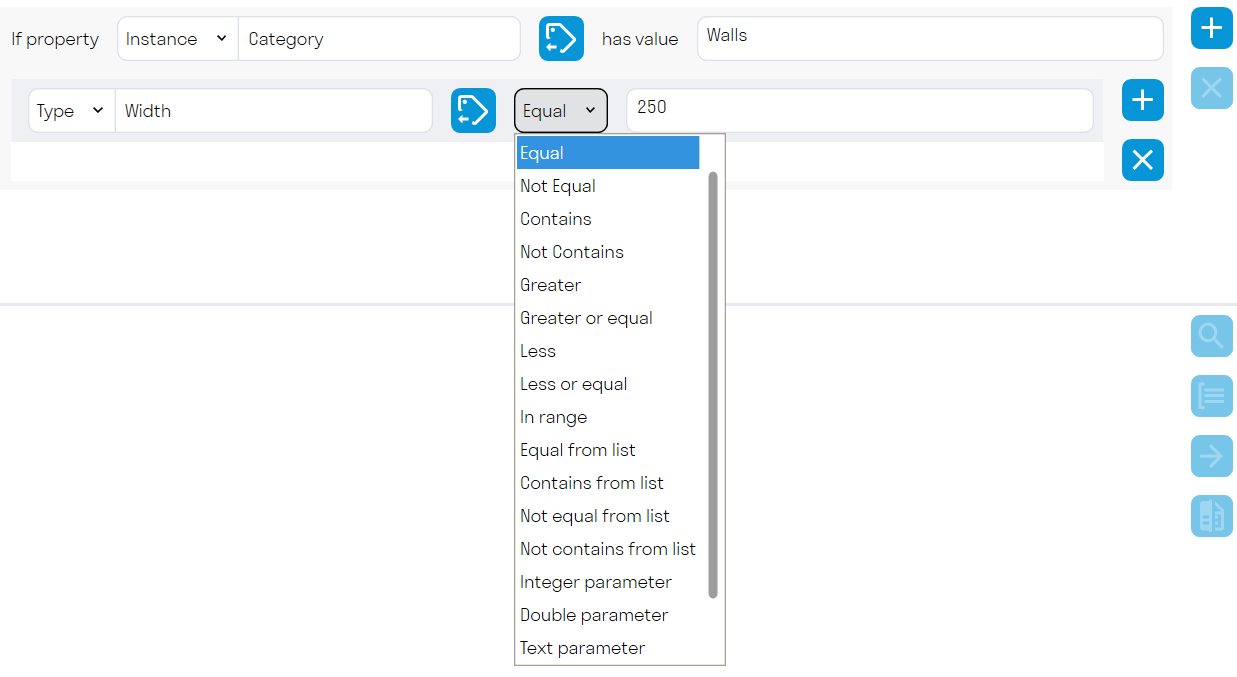
Operators
-
"Equals" (=) and "Not Equals" (!=) - The check is considered passed if the value of the property being checked fully matches or does not match the specified value. Both numerical and string values can be specified.
-
"Contains" (?) and "Does Not Contain" (!?) - The check is considered passed if the value of the property being checked contains or does not contain the specified string value.
-
"Greater Than" (>) and "Less Than" (<) - The check is considered passed if the value of the property being checked is greater than or less than the specified numerical value.
-
"Greater Than or Equal To" (>=) and "Less Than or Equal To" (<=) - The check is considered passed if the value of the property being checked is "greater than or equal to" or "less than or equal to" the specified numerical value.
-
"In Range" - The check is considered passed if the value of the property being checked is within the specified range. The range is defined by two numbers (minimum and maximum) separated by two periods. In Excel, the value is written as: [value1..value2]
-
"Equals from List" and "Not Equals from List" - The check is considered passed if the value of the property being checked fully matches one of the specified values. Both numerical and string values can be specified. List multiple values separated by commas without spaces. If the specified values can be converted to numbers, they will be checked as numbers. The value is written in Excel as: [value1,value2] or ![value1,value2]
-
"Contains from List" and "Does Not Contain from List" - The check is considered passed if the value of the property being checked contains or does not contain at least one of the specified string values. List multiple values separated by commas without spaces. In Excel, the value is written as: ?[value1,value2] or !?[value1,value2]
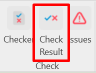
Check result
The tool allows you to display elements in the current model based on the check results, which can be done using the Checker command in Navisworks. This is a convenient way to edit elements that must be corrected based on the check results.
- Click on the Check panel ➔ Check Result.
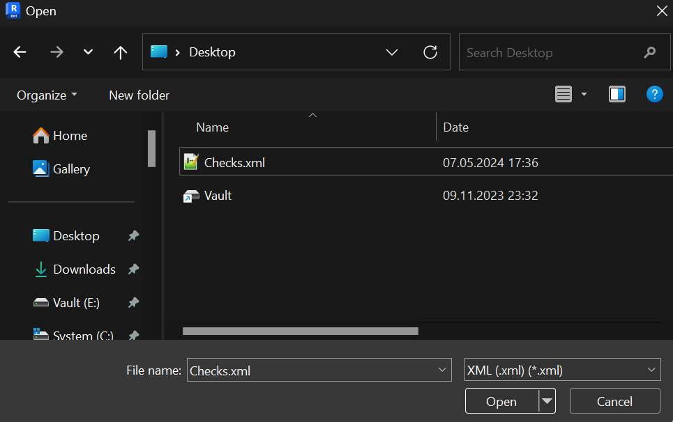
- Select the XML file with the check result and click "Open".
- The elements that failed the check will be highlighted in the model.
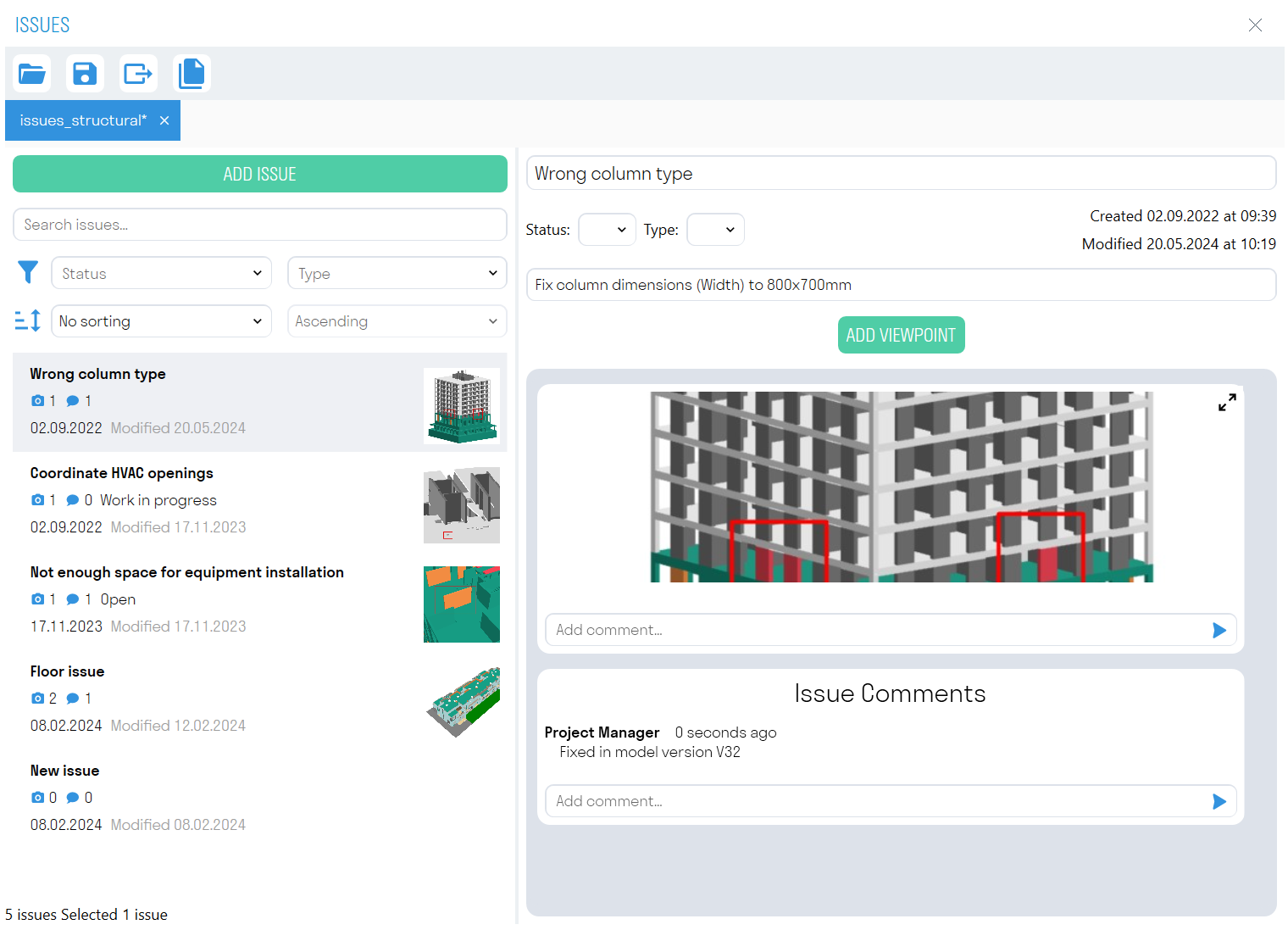
Issues
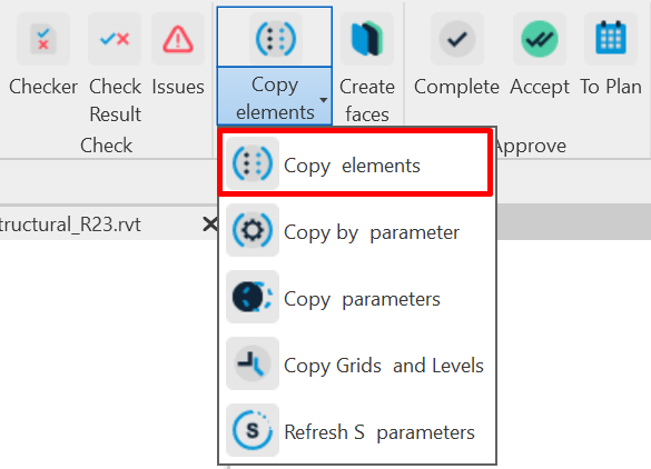
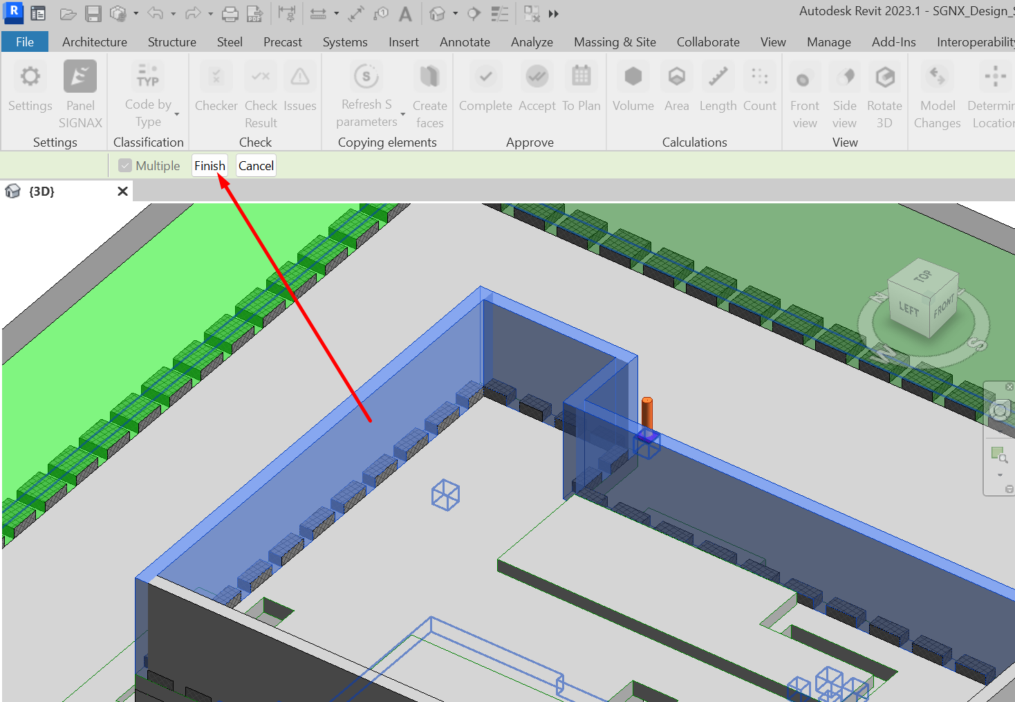
Copy elements
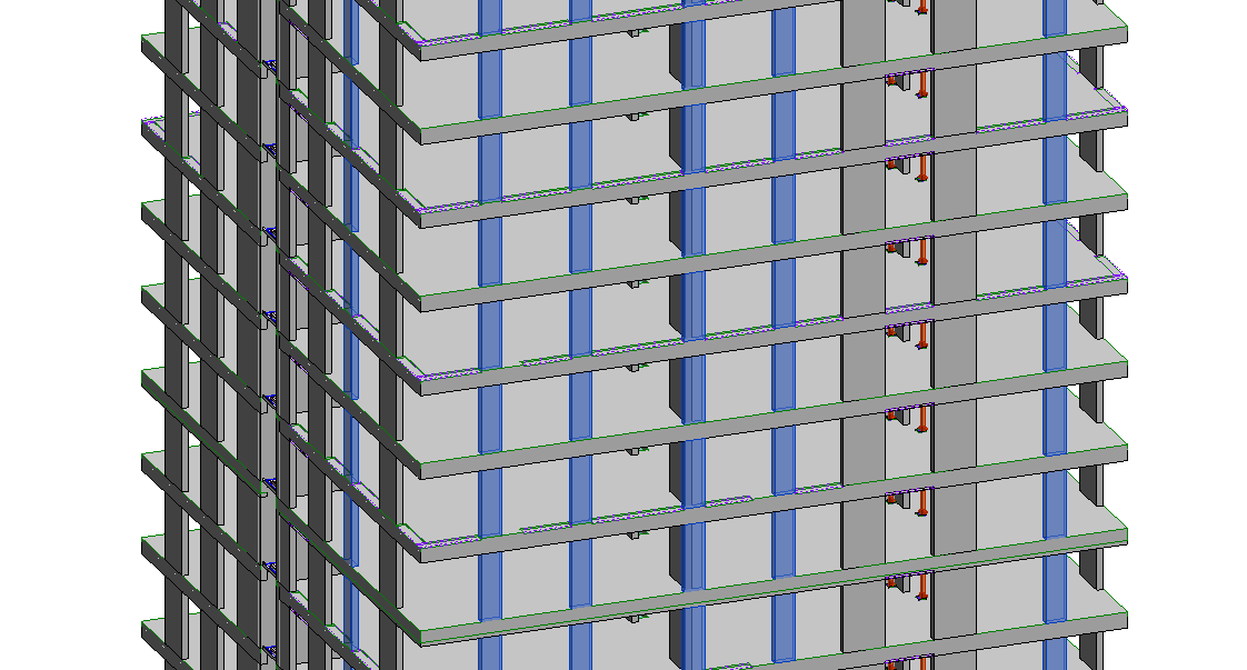
The "Copy Elements" tool is designed to copy elements from a linked file. When copying, non-editable geometry with parameters is created in place of the element. Before copying elements, it is recommended to specify additional parameters that should be copied along with the geometry. Copying is performed in the "1. Copying Elements" view. It is recommended to use the Construction Model template.
Click on the Copy Elements panel ➜ Fix Elements.
Function Settings Window
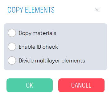
- The "Copy Materials" toggle controls the visual display of materials on the copied geometry. It is recommended to keep it off since copying with materials increases the overall command execution time.
- The "Enable ID Check" toggle prevents duplication of previously copied elements. If it is necessary to replace previously copied elements, delete the outdated version of the element before copying. Replacement of an element entails replacing its ID in the construction model; thus, due to the change in ID, Navisworks won't be able to pull SIGNAX data into the new element.
- The "Divide multi-layer elements" toggle divides a multi-layered wall into layers and copies each layer as a Part category.
-
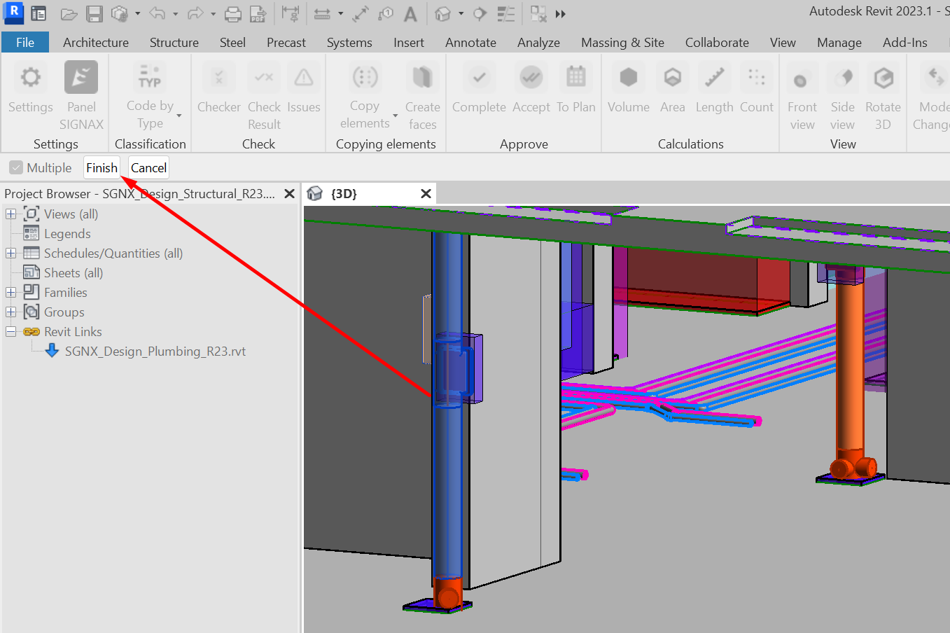
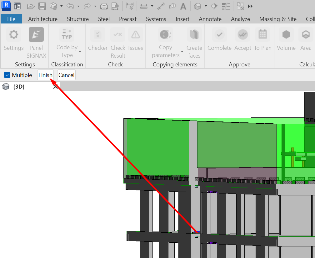
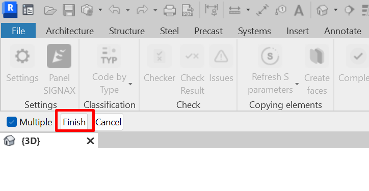
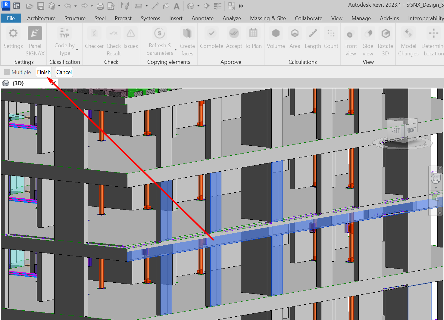
Select elements from the linked model that need to be copied, and click "Finish" the top left corner.
-
The selected elements will be copied from the linked file and appear in the "2. Construction Model Creation" view. The elements will represent non-editable geometry (DirectShape) with parameters.

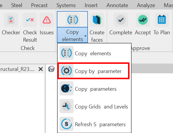
Copy by parameters
The "Copy by Parameter" tool is designed to copy elements from a linked file based on specific parameters. When copying, non-editable geometry with parameters is created in place of the element. Before fixing elements, it is recommended to specify additional parameters that should be copied along with the geometry. Copying is performed in the "1. Copying Elements" view. It is recommended to use the Construction Model template.
-
Click on the Copy Elements panel ➜ Fix by Parameter.
-
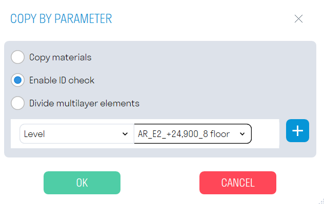
The tool settings window will open. Add parameters by clicking "+". In the parameter line, select the parameter name and value based on which elements will be copied from the linked model.

The "Copy Materials" toggle, "Enable ID Check" toggle, and "Create Construction Pie" toggle function similarly to those in the previous tool.
-
Elements with the specified parameters will be copied from the linked file and appear in the "2. Construction Model Creation" view. The elements will represent non-editable geometry (DirectShape) with parameters.

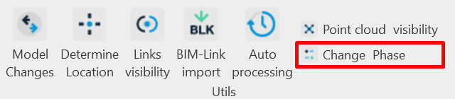
Change phase
The "Change phase" function is intended to display completed elements on the construction site in the "3. Construction Model (Navisworks)" view. The command changes the value of the "Construction Stage" parameter in the selected element to the value specified in the SIGNAX Settings under General (by default, this is "Completed").
-
Open the "2. Construction Model Creation" view and select the elements that are actually completed on the construction site.
-
Click on the Utilities panel ➜ Toggle Stage.
The selected elements will be colored green in the "2. Construction Model Creation" view and will appear in the "3. Construction Model (Navisworks)" view.
Note: For manual stage switching in the "Properties" of elements, find the "Construction Phase" parameter and change it from "Project Model" to "Completed".
Note: For manual stage changes in parts, it is necessary to uncheck the "Construction Stage as per Source" option.
Complete/Accept/To Plan
Using the commands Complete, Accept, and Schedule, you can assign the corresponding status to fixed elements.
1. Click on the Acceptance panel ➜ Complete/Accept/To Plan.
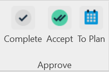
- Complete - actual completion date.
-
Accept - Approved and paid work (Invoice date)
-
To Plan- planned date with contractor assignment.
2. Select the elements to which you want to assign a status, and click Done in the top left corner.
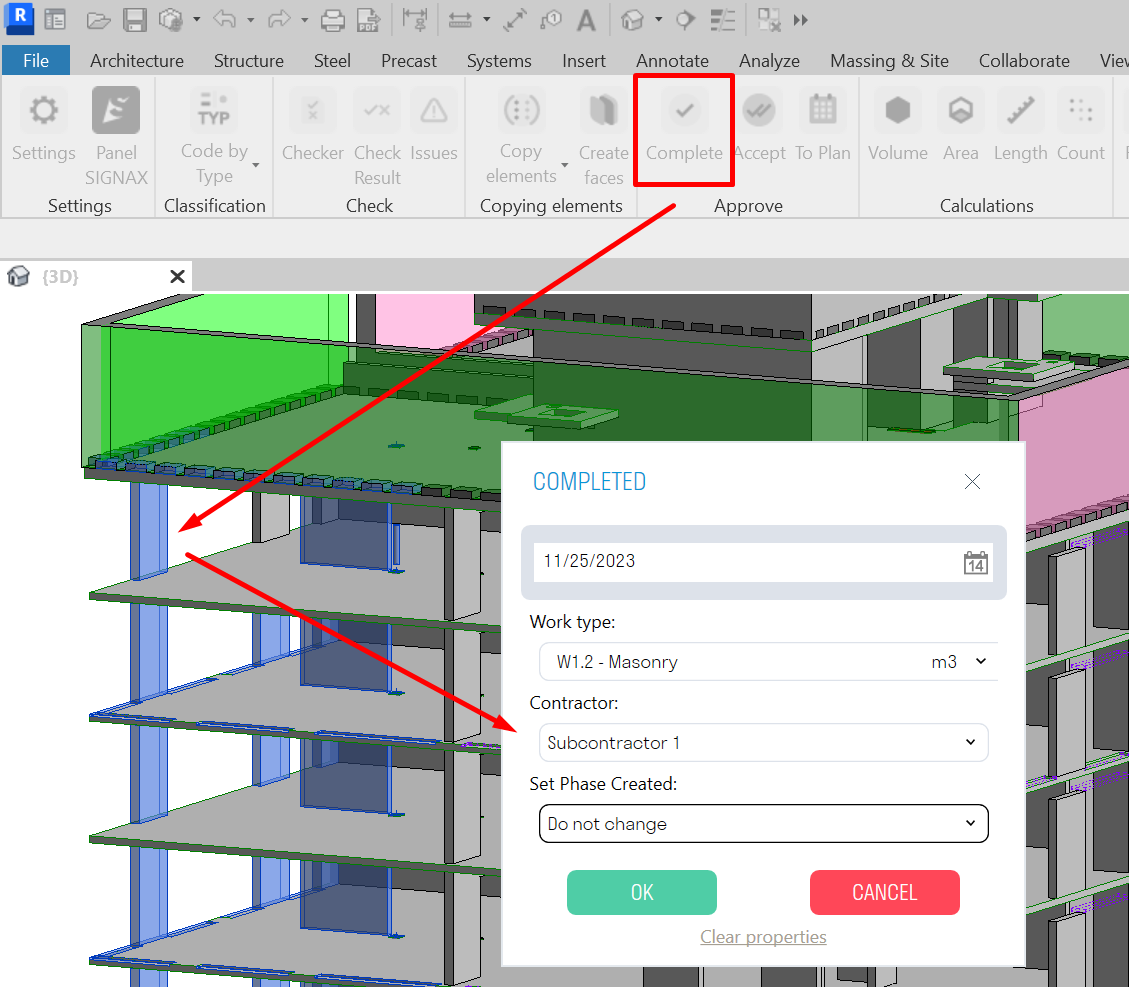
The settings windows for the Complete/Accept/Schedule commands look the same.
-
In the "Date" field, specify the completion/acceptance/scheduling date of the work.
- In the "Type of Work" field, select from the list the type of work associated with the element.
Works can be added in two ways - manual entry or Excel table import (see "Setting Work Types" for more details).
-
In the "Contractor" field, select from the list the company performing the specified type of work. You can add a company in the SIGNAX plugin settings (see "Setting Companies" for more details).
-
In the "Set Construction Phase" field, specify the construction stage as "Completed". After that, the elements actually completed on the construction site will appear in the "3. Construction Model (Navisworks)" view.
- The "Clear Properties" button removes the parameter values from the selected elements.
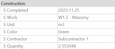
3. After assigning the status, the corresponding parameters "S Completed", "S Accepted", and "S Planned" appear in the properties of the selected elements in the "Construction" section. Additionally, the following parameters appear:
- "S Work" - Work name;
- "S Unit" - Measurement units;
- "S Color" - Color;
- "S Contractor" - Contractor;
- "S Quantity" - Quantitative characteristic, calculated depending on the units of measurement.

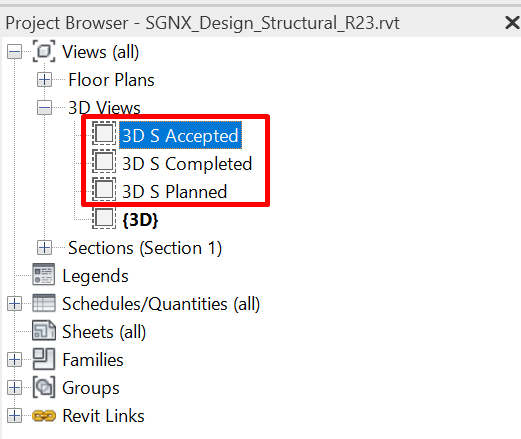
Views "3D S Completed", "3D S Accepted", and "3D S Planned" are created, where elements with the corresponding status are marked in color (Completed - Green, Accepted - Purple, Planned - Blue).
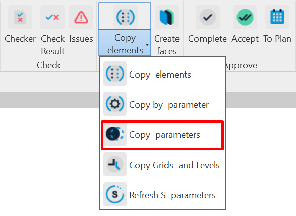
Copy parameters
Using the Copy Parameters command, you can copy missing parameters for already fixed elements.
- Click on the Copy Parameters panel ➤ Copy Parameters
Tool Settings Window
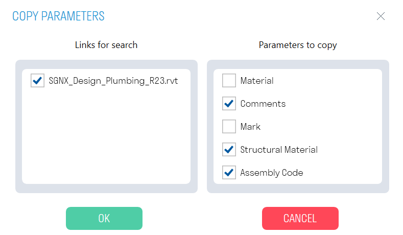
- In the "Search Links" block, specify the linked model from which parameters need to be copied.
- In the "Parameters to Copy" block, specify the parameters that need to be copied from the linked file. Parameters for copying are filled in the SIGNAX Settings under the Parameters to Copy section.
- Select the elements for which parameters need to be copied, and in the top left corner, click Done.
Copy grids and levels
The command allows you to copy grids and levels from a linked file into the construction model. This is necessary for creating plans based on the levels of the project model or for dividing elements into parts along the axes.
- Click on the Copy Elements panel ➜ Copy Grids and Levels.


The tool settings window.
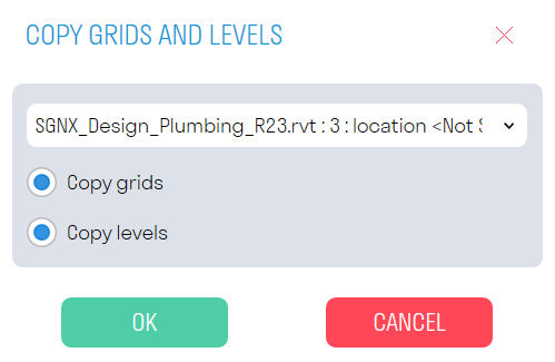
- Specify the linked file from which the axes and levels will be copied.
- The "Copy Axes" toggle is responsible for copying axes.
- The "Copy Levels" toggle is responsible for copying levels.
Refresh S parameters
The tool updates the geometric parameters (S Volume, S Area, S Length) and S id history for elements in the Parts category. This is required when the geometry of an element is changed.
- Click on the Copy Elements panel ➤ Refresh S Parameters
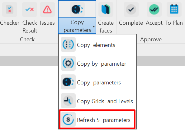
- Select the elements in the Parts category for which parameters need to be updated, and click Finish.
Create faces
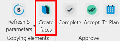
The tool allows you to create surfaces from selected faces. It can be used to create an accumulative construction model for facades or interior finishing when they are constructed as single-layer walls or not modeled.
- Click on the Copy Elements panel ➤ Create Surfaces
Tool Settings Window
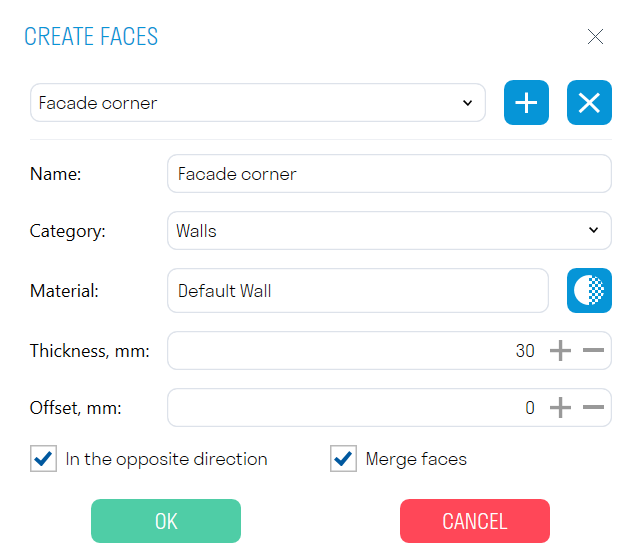
You can add and remove different surface options with their parameters.
- In the "Name" field, specify the name of your option.
- In the "Category" field, choose the category of the surface to be created.
Note: Some categories are not suitable for creating surfaces, such as Analytical Column Models or Concentrated Loads.
- In the "Material" field, select the material of the created surface.
- In the "Thickness" field, specify the thickness of the surface in mm.
- In the "Offset" field, specify the offset of the surface from the selected face in mm.
- The "Reverse Direction" toggle allows you to choose the direction in which the surface will be extruded.
- The "Merge Faces" toggle allows you to build the surface as a single entity when selecting multiple faces.
- Select one or more faces and click Done.
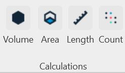
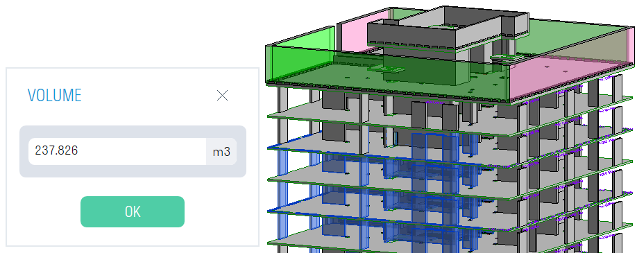
Volume/Area/Length
Using the Volume, Area, Length, and Quantity commands, you can obtain values of corresponding parameters for elements. The parameter names from which values are to be collected are set in the SIGNAX Settings in the Quantitative Property section.
-
Select the element/elements and click on the Calculations panel ➜ Volume/Area/Length/Count.
-
Obtain the corresponding value.


Model changes
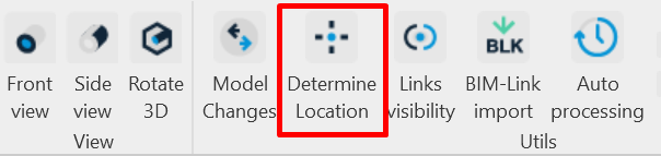
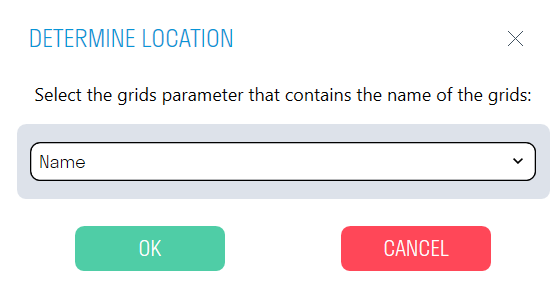
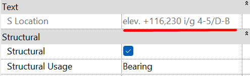
Determine location
The tool allows you to determine the location of model elements relative to the level and the nearest grid axes, with the result recorded in the parameter "S Location."
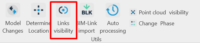
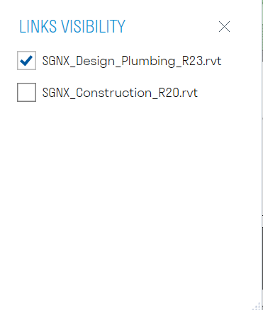
Links visibility
The tool allows you to manage the visibility of links in the current view, similar to the Linked Files tab in Visibility/Graphics Overrides, which can be assigned to a hotkey.
- Click on the Utilities panel ➤ Link Visibility
- Uncheck the checkbox next to the linked file that needs to be hidden in the current view.
BIM-Link import
Autoprocessing
The command helps BIM engineer automate the process of exporting and checking Revit models located both on the local computer and on the Revit server. The plugin, at the specified time without the specialist's involvement, saves RVT files to the specified directory, exports them to NWC and IFC formats, checks them with the "Checker" command, and classifies the models using "Code by Condition".
Note: The plugin can be launched from any Revit file, even an empty one. The version of the processed Revit files must match the version of Revit from which the plugin is launched. Do not close the tool or turn off the computer until the Auto-processing process is complete.
-
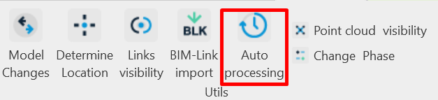
Click on the Utilities panel ➜ Auto-processing.
-
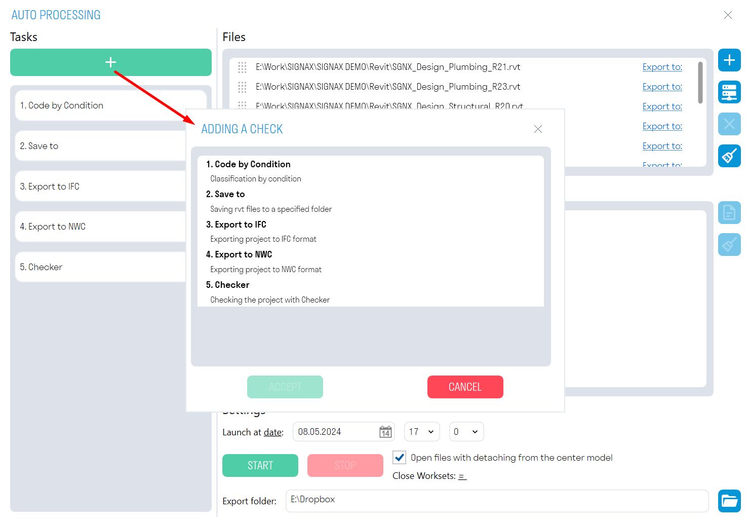
In the "Tasks" window, click "+" and add actions that will be performed sequentially on the selected files.


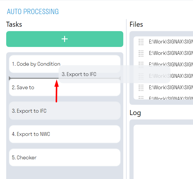
The order of task execution can be changed by dragging them.
"Code by Condition" assigns a code according to the classifier to all elements based on certain conditions. The rules are taken from the file from which Auto-processing is launched.
Note: Use this task with the "Open files with detach from central model" option turned off. Otherwise, all changes will not be saved in the original file.
"Checker" checks the selected models for the presence of parameters in elements and the completeness of parameter values. The results of the check are Excel files with check results. The checking rules are taken from the file from which Auto-processing is launched. In the "Checker" tool, you need to check the boxes next to the performed checks.
"Save to" saves the selected files in RVT format to the specified directory. For collaborative work models, it is recommended to use the "Open files with detach from central model" option.
"Export to NWC" exports the selected models to NWC format to the specified directory, using the current export settings. The export takes place from the "Navisworks" view. If there is no Navisworks view in the file, the export will be performed from the first view containing the word "Navisworks", for example, "BIM_Navisworks" or "Navisworks ARCH". If there are no suitable views in the file, the entire model will be exported.
"Export to IFC" exports the selected models to IFC format to the specified directory.
Note: The export directory is specified in the "Export folder" field at the bottom of the window.
-
In the "Files" window, click
 to select RVT format files from the local computer, or
  to select files from the Revit server. The previously specified tasks will be applied to the selected files.
 -
The "Settings" window contains various options for launching Auto-processing.


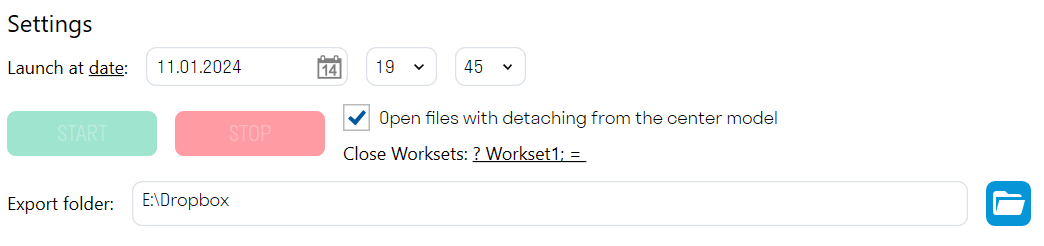
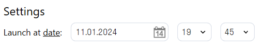
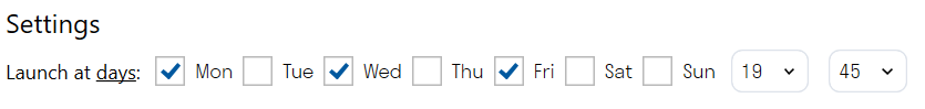
- You can choose to start by date or by days.
For one-time model processing, use the date-based launch. The plugin will run once at the specified date and time.
For regular file processing, select the day-based launch. The plugin will run on the specified days at the same time.
The "Open files with detach from center model" option allows you to open models with detachment from the collaborative model. This is necessary when saving such models in RVT format for further transmission, for example, to the client.
Note: This option should only be used with export commands, as changes made by the "Code by Condition" command will not be saved in the original file.
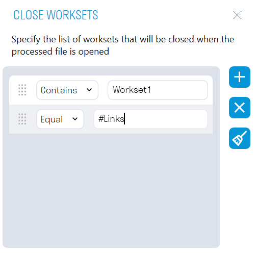
"Close Worksets" allows you to close the specified worksets when opening the processed file. For example, you can close the workset with linked files to make the processed models open faster.
The export directory specifies the directory for exporting files.

- After setting up the launch, click "START". At the specified time, the plugin will start sequentially opening the selected models and performing the specified tasks on them. Do not close the tool or turn off the computer until the Auto-processing process is complete.
The plugin's operation process can be observed in the "Log" window. Here, all the results of the performed actions and errors that occurred during auto-processing will be recorded. The results can be opened in .txt format by clicking  and saved to the local computer.
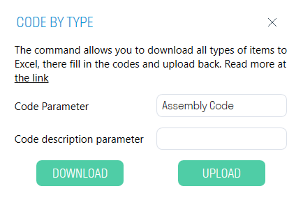
Code by type


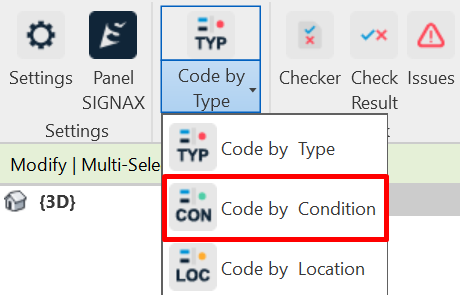
Code by condition
The command allows assigning classification codes to all elements based on specific conditions. It can fill in both type parameters and instance parameters. For example, you can assign a code and code description for elements in the category "Load-bearing columns" located on the fifth floor.
1. Click on the Classification panel ➜ Code by Condition.
Command Settings Window:
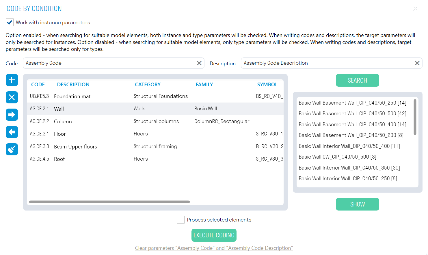
- The "Work with Instance Parameters" toggle allows you to write the code and code description into instance parameters or type parameters.
- The "Process Selected Elements" toggle allows you to write the code and code description into manually selected elements.
- In the "Code" and "Description" rows, enter the names of the parameters where the classification code and code description will be recorded, respectively. These can be either instance parameters or type parameters.
2. You can add and fill in rules for model classification directly in the plugin, or fill in the rules in an Excel table and import it.
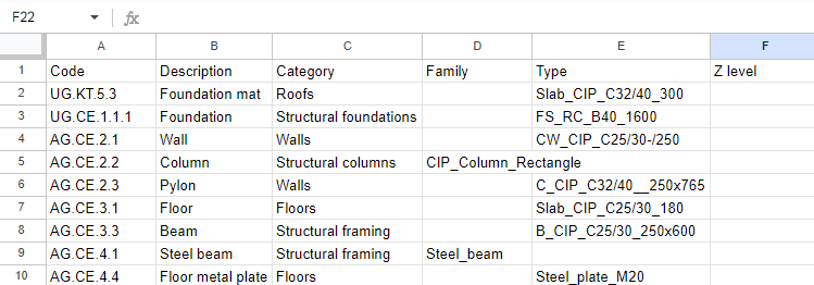
Excel Table Structure for Classification Rules:
-
In the "Code" column, enter the classification code that needs to be assigned to the elements.
-
In the "Description" column, enter the description of the code. In the "Category" column, enter the category of elements related to the code.
-
In the "Family" column, enter the name of the family to which the classification code should be assigned (Fill in as needed).
-
In the "Type Size" column, enter the name of the type size to which the classification code should be assigned (Fill in as needed).
-
In the "Z level" column, enter "+" if you need to assign codes to elements above level 0.000, or enter "-" if you need to assign codes to elements below level 0.000 (Fill in as needed). In the "Parameter" column, enter an additional parameter by which elements should be classified.
-
In the "Condition" column, enter one of the operators (Equals: =), (Not equals: !=), (Contains: ?), (Does not contain: !?).
-
In the "Value" column, enter the parameter value.
Note: The "Parameter," "Condition," "Value" columns specify one additional condition for classifying elements. Specify these columns as many times as additional conditions are required.
3. To preview the elements that match the specified classification rules, select the rule and click SEARCH.
4. To display an element in the model, select the element and click SHOW.
5. Click Execute Coding ➜ the plugin will write the code and code description into the specified parameters.
Code by location
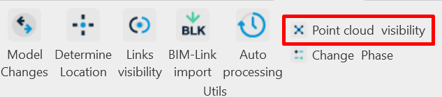
Point cloud visibility
The command allows toggling the visibility of point clouds on the current view. For convenience, you can assign a shortcut key to the tool.
- Click on the Utilities panel ➜ Point Cloud Visibility.

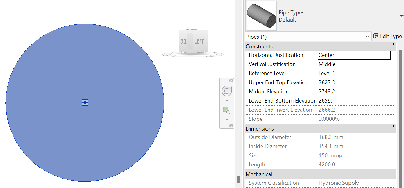
Front view
Front View The tool allows orienting the 3D view along the cross-section of the selected linear object (pipes, ducts, trays). This tool is useful when you need to view a linear object from the front that is not orthogonal to the main axes (X, Y, Z).
-
Click on the View panel ➜ Front View.

-
Select the linear element. The 3D view will rotate.

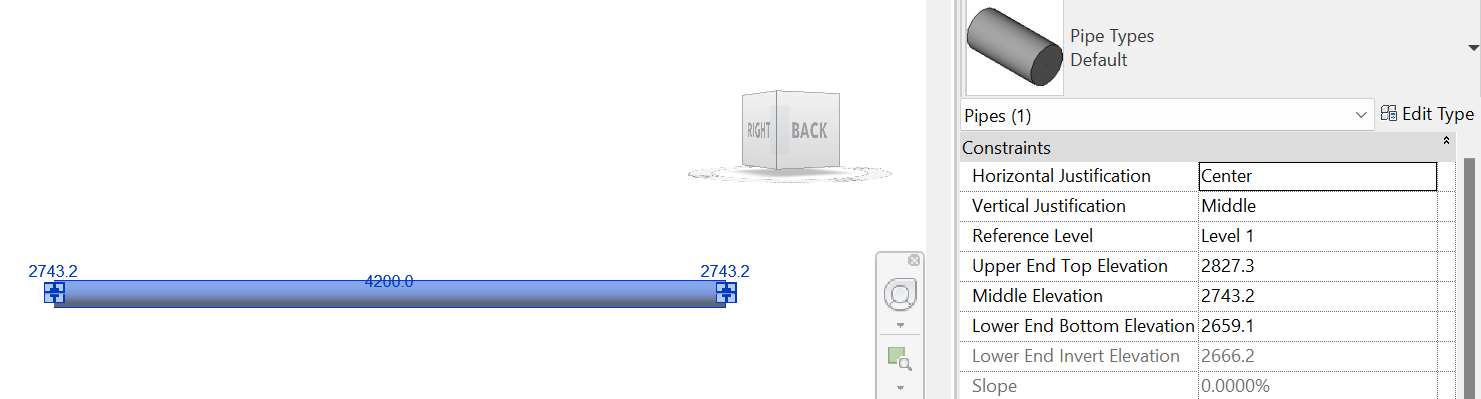
Side view
Side View The tool allows orienting the 3D view along the longitudinal section of the selected linear object (pipes, ducts, trays). This tool is useful when you need to view a linear object from the side that is not orthogonal to the main axes (X, Y, Z).
-
Click on the View panel ➜ Side View.

-
Select the linear element. The 3D view will rotate.

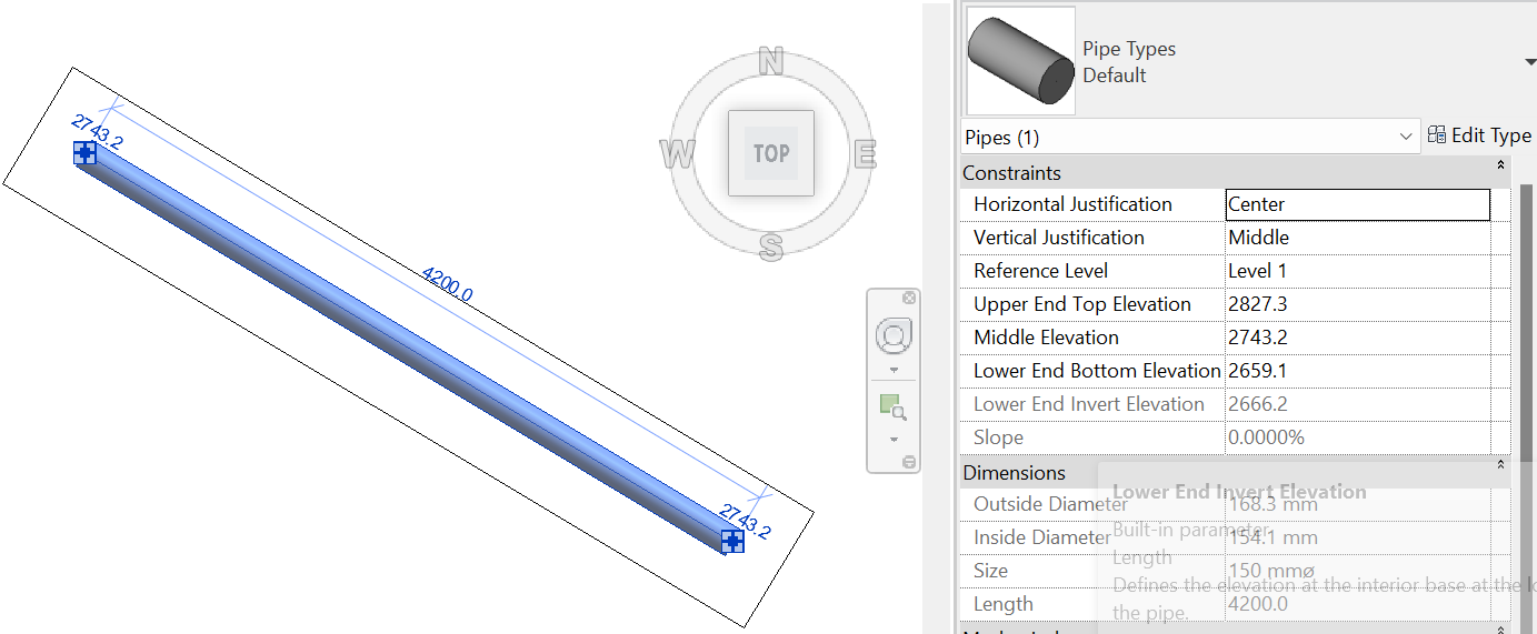
Rotate 3D
Rotate 3D The tool allows rotating the 3D view clip boundary along the linear object.
-
Click on the View panel ➜ Rotate 3D.
-
Select the linear element. The clip boundary will rotate along the element.


No Comments