3.4.1.4. 4D BIM model manual
This manual is for SIGNAX specialists working with a 4D model based on project models and a Microsoft Project construction schedule.
Create Revit file and divide the object
Initial data:
1. Revit Project model.
2. Microsoft Project Construction Schedule
Tools:
-
Software: Autodesk Revit, Navisworks Manage, Microsoft Project, Excel;
-
SIGNAX for Navis Plugin;
-
SIGNAX for Revit plugin;
Create Revit file:
1. Open Autodesk Revit. Create a project based on the construction template and link the project model.
2. Create mass based on the location of the element groups (building, section, floor)


Copy forms to typical floors by clicking the "Copy" button. Then create new form elements for non-typical floors:
Important: each mass element must be within the height of the floor, in width and length - within the building to which it will belong. [Number of mass objects] = [Number of floors in section 1] + [Number of floors in section 2] + ... + [Number of floors in section n]. If all sections have the same number of floors, you can create a mass form for all sections and then, when writing parameters, change the "Section" parameter.
Object divide structures can differ for discipline models ARCH, STR and MEP. For example, one package of the ARCH model includes half of the floor below the floor elevation and the vertical structures of this floor. The STR package consists of the vertical structures of the floor, and the floor slabs above the current floor. There is also a divide for facades that goes from bottom to top for each facade.
In the created form copies, fill in the previously added parameters: Building, Section, and Floor.
"Case" = B01 Parameter(Since the result models refer to Building 1). Prefix B - means Building. This parameter has been implemented to use filtering and grouping by "Contains B01" in other programs. The number consists of two digits to avoid the following result: 1,11,12,2,3...
Parameter “Section” = S02. S - means Section.
The "Floor" parameter is filled with the following values: L-1, L01, L02, L03, T01 (for a technical floor) ... it is possible to fill in F01, F02 ... - for facades, A01 ... - for foundations, Z01 ... - for the roof.

6. You can check if all parameters are filled by creating Mass specification.
You can edit Values here:
.png?alt=media&token=c79ed435-142b-4f9d-9cd8-c5b396f56c82)
7. Save the mass model with a specific name.
Copy parameters from a Mass model to a Work model
1. Open the Project Model you used to create the Mass.
2. Add the parameters "Building", "Section" and "Floor" to all categories of elements that you are going to upload to Navisworks as you did in step 3 of Create Revit file and divide the object.
Ex.: Select all elements in Navisworks 3D view and filter all existing element categories:

Click "Insert" and choose "Insert from File" - "Insert Views from File". Select "Specifications" and click "Select all".


Ex.: thiis how you can apply parameters "Code1'. "Code2", "Code3", "Work1", "Work2", "Work3" to all necessary categories
4. Fill in the parameter "Work1" in all elements("Work2", "Work3" - they exist to divide works by different criteria in case if by Assembly Code they have the same type). The fastest way to do it for some elements is through the Export to Excel.
How to fill the Work parameter in Excel:
а) Open the "Project Manager" and find "Sheets/Specifications”:
b) Choose “W_Several Categories” specification, go to the Sort/Group settings in the specifications' properties and sort by Family and Type, select "For each instance" and click OK.
с) Export specification with “10.01_Export to Excel” script: Choose "Manage" and click "Dynamo Player".
d) Fill the "By type of work" parameter for all elements(except for holes) in the exported specification:
f) Apply this step to all specifications. Create your own specifications if needed, and follow the previous steps.
Important! Ensure that all the "Work" parameter specification lines have been filled and assigned to all elements. You can check this with export to Navisworks. Choose "File" - "Export" - "NWC":
(Download file for export from Revit to .nwc: https://www.autodesk.ru/products/navisworks/autodesk-navisworks-nwc-export-utility)
Click "Navisworks Settings..." - "Reading Files" - "Revit", choose "Current view" for "Export", click "ОК".
Open Navisworks. Click "Home" - "Select" - "Selection Tree" - "Find Items", select neede and press "Find All".
If all work codes are assigned to all elements, you can go back to the working file in Revit. If there are elements without codes, then analyze and fill the parameters in Revit.
g) Upload the Mass model into project(By Shared Coordinates).
Ex.: If the link is loaded but not visible, check the Working Set it was loaded in and transfer it to the visible working set in the Navisworks view if necessary.
5. Launch “10.03_Fill the codes” script. Choose link with Mass. The parameters "Code1", "Code2", "Code3", "Building", "Section", and "Floor" will be filled after running the script:
It should look like this:
6. Export Navisworks 3D-view in .nwc:
8. Repeat the previous steps with all Building files if needed.
Final 4D model design
-
To create a federated model, launch Navisworks Manage 2020. Click the "Add". Select the path to the NWC folder, change the "Files type" to "Navisworks Cache (* .nwc)". Select the files you need for the federated model and click "Open".
-
Now you need to create search sets according to the Code parameter using the SIGNAX for Navis plugin "Sets from Excel".
To create Search Sets automatically, use the Plugin and follow the next steps:

Ex.:
this Excel-file contains folders names
F1
F1.0
F1.0.0
F1.0.1
where F = Folder - folder with Search Sets.
The second column has folder names, displayed in the Search Sets manager.
Search sets have a code in the first column identical to the folder code but replaced with the letter W (means Work).
So, the work that should be in the F1.0.1 folder will have the code W1.0.1.
Next, fill the search set "Name" in the search set manager.
Column C indicates the properties tab in the "Object Properties" with searched parameters.
Column D has a parameter to filter elements by the parameter value.
Column E contains the parameter value used by the search set to select items.
Column F indicates the condition used for the elements search:
“=” - equal;
“?” - contains;
“!=” - not equal;
“d” - specific.
After, the alternated parameters for filtering by the "AND" condition.
b) Load the Excel file and check if all the elements are included in the search sets with the "Hide" tool
Ex.: to works with Search Sets, open the "Sets" window and select the search sets you need (use Shift and Ctrl).
Update the search set if necessary. For this, you need to open the "Find Items" tool and select the search set you need. Then, correct the rules, right-click on the search set and left-click on "Update".
3. Next, import the construction schedule into MS Project. Or create a simplified work schedule based on the existing work schedule.

TimeLiner и Excel columns match setting:

After adding a data source (MS Project construction schedule), right-click on the line with the schedule and select "Rebuild task hierarchy" to display the schedule structure in the "Tasks" tab.
5. It is necessary to attach elements to the TimeLiner tasks according to the search sets for the graphics visualizing. If names assigned to "Task Names" in graphics and Search Sets are the same, Navisworks Manage can automatically attach Tasks to Sets. To do this, click the "Auto-attach" in the Timeliners "Tasks" tab, and select "Display Timeliner tasks from the Name column to the same name Object Sets, case "Matching"":

Blue notes for attaching search sets will appear in the Attachments column of the Timeliner Tasks tab. Search sets are attached according to the matching sets' names and tasks in the chart.
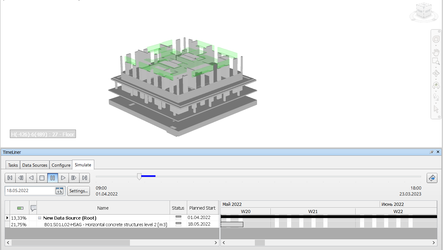
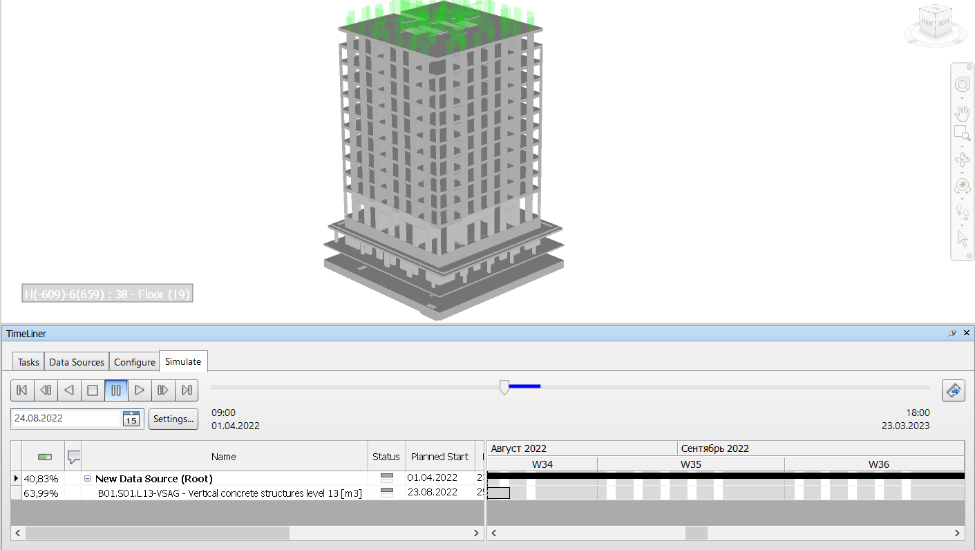
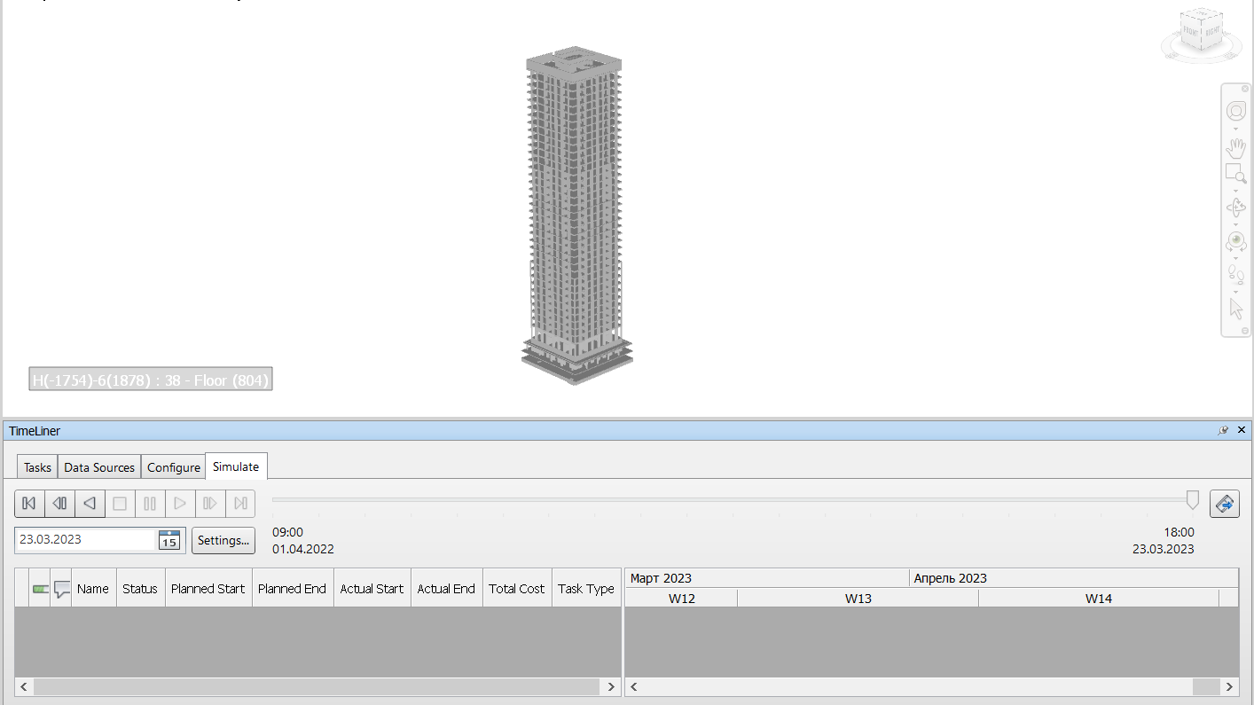
6. In the "Modeling" tab, you can see the construction schedule by day, including planned and actual construction progress:
Terms and Definitions
Terms and Definitions
Work Models
.RVT format models. Designers work with them to get blueprints(sheets) from these models. They are located on the designer server, Revit server, or Autodesk Construction Cloud.
Common Data Environment
Cloud space for access rights managing. You can upload any project files. Access is possible from anywhere, via an Internet connection. Usually, it is possible to change file statuses, note issues based on files, and review project documents and models.
Uploaded Models
These are models uploaded to the common data environment for verification, approval, transfer of a particular phase of work.
Object structure model
Created with Mass elements RVT model (tool "Mass"). This model shows the building's structure used to divide elements and works they are linked to.

NWC Models
Exported Revit models ("File" - "Export" - "NWC")
Search Sets
Selection of elements according to specific rules. Search sets allow you to select items according to certain rules. You can synchronize search sets with the construction schedule positions(if they match by name).
Timeliner Construction Schedule

This tool allows you to link model to MS Project/Primavera construction schedule. Visualize the construction process and display the specific date budget amount. This tool also shows schedule deviation and highlights the schedule lag. To do this, you must indicate the actual close in the MS Project schedule.Federated Model
.NWF model(Navisworks Manage). This model contains all phases models(from Revit) at NWC format. Federated model has all the Search Sets settings and Construction Schedule links.
Transfer Federated Model to NWD
You can save the working NWF file in NWD format to transfer the model version. However, you can't use an NWD federated model as a Working model(cause it is a detached version of the model as of a specific date).
No Comments