< TOOLS FOR REVIT. Copying elements | TOOLS FOR REVIT. Approve >
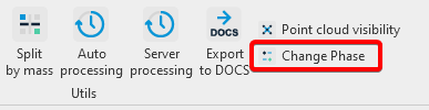
The Change Phase tool is designed to display elements completed on the construction site in the “3. Construction Model (Navisworks)” view. The command changes the “Construction Stage” parameter for the selected element to the value specified in the SIGNAX Settings in the Main section (by default, this is “Completed”).
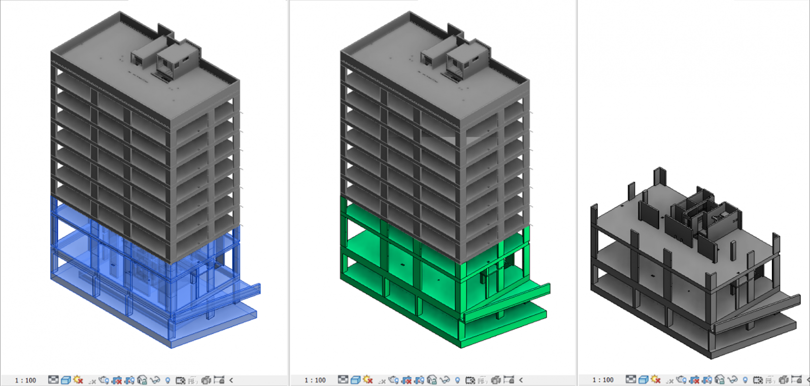
1. Open the “2. Construction Model Creation” view and select the elements that are actually completed on the construction site
2. Click on the Utilities panel ➤ Change Phase
The selected elements will turn green in the “2. Construction Model Creation” view and will appear in the “3. Construction Model (Navisworks)” view.
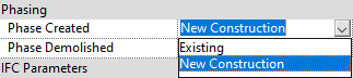
Note: To manually Change the phase in the "Properties" of the elements, find the "Construction stage" parameter and change it from "Project model" to "Completed":
Note: To manually change the stage of the parts, you need to uncheck the "Construction stage by original" item:
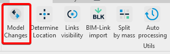
The tool allows you to highlight elements in the construction model that have been changed in the updated version of the design model using the SIGNAX plugin for Revit
1. Click on the Utilities panel ➤ Model Changes
2. Upload the CSV file obtained from BIM 360 Docs (ACC Docs) (see details “Definition of changed elements in CM” )

3. The S Compare parameter is added to the changed elements. In the view “4. Changes in the model”, the changed elements are colored according to the value of the S Compare parameter

- Removed - Removed
- Added - Added
- Geometry - Geometry change
- Move - Position change
- Parameter -Parameter change

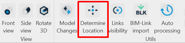
The tool allows you to determine the location of model elements in relation to the level and the nearest axes of the axes grid with the result written to the “S Location” parameter
1. Click on the Utilities panel ➤ Define location
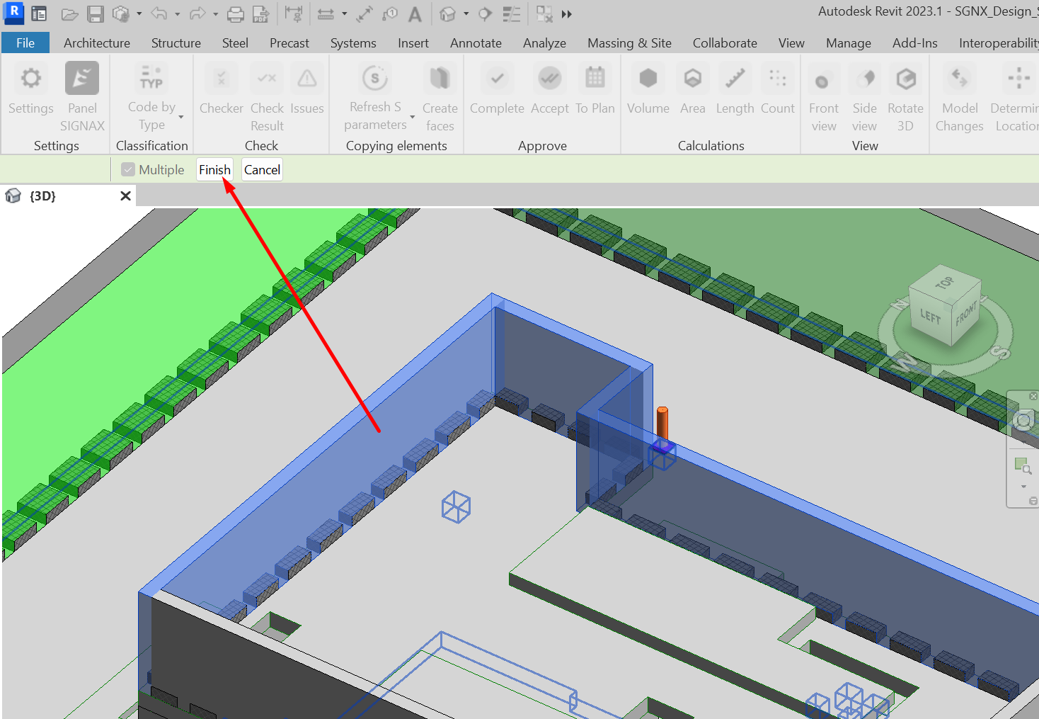
2. Select the model elements and click Done in the upper left corner
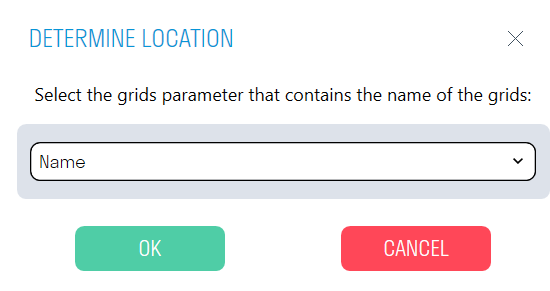
3. Select the axis parameter from the list that contains the name of the axes. For example, the Name parameter.
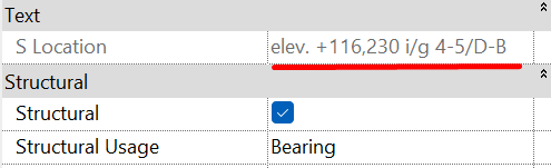
4. The “S Location” parameter is created for the selected elements, which specifies the location of the element in the axes and the element elevation in meters. For example, elevation +23,340 m, in axes 1.1-2, in axes B.1-G
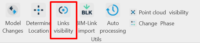
This tool allows you to manage the visibility of links in the current view. Analogous to the Linked Files tab in Visibility/Graphics Overrides, which can be assigned to a hotkey.
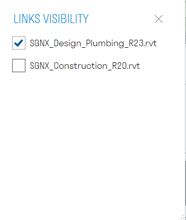
1. Click on the Utilities panel ➤ Link Visibility
2. Uncheck the linked file you want to hide in the current view
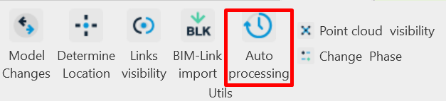
This tool helps BIM professionals automate the process of uploading and checking Revit models located both on the local computer and on the Revit server. The plugin, without any specialist intervention, saves RVT files to the specified directory at the specified time, uploads them to the NWC and IFC formats, checks them with the "Checker" command, and classifies the models using the "Code by Condition" function.
Note: The plugin can be run from any Revit file, even an empty one. The version of the Revit files being processed must match the version of Revit from which the plugin is run. Do not close the tool or turn off the computer until the AutoProcess process is complete.
1. Click Utilities ➤ AutoProcessing
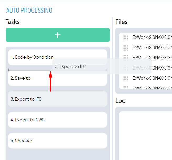
2. In the "Tasks" window, click + and add actions that will be performed on the selected files in order.
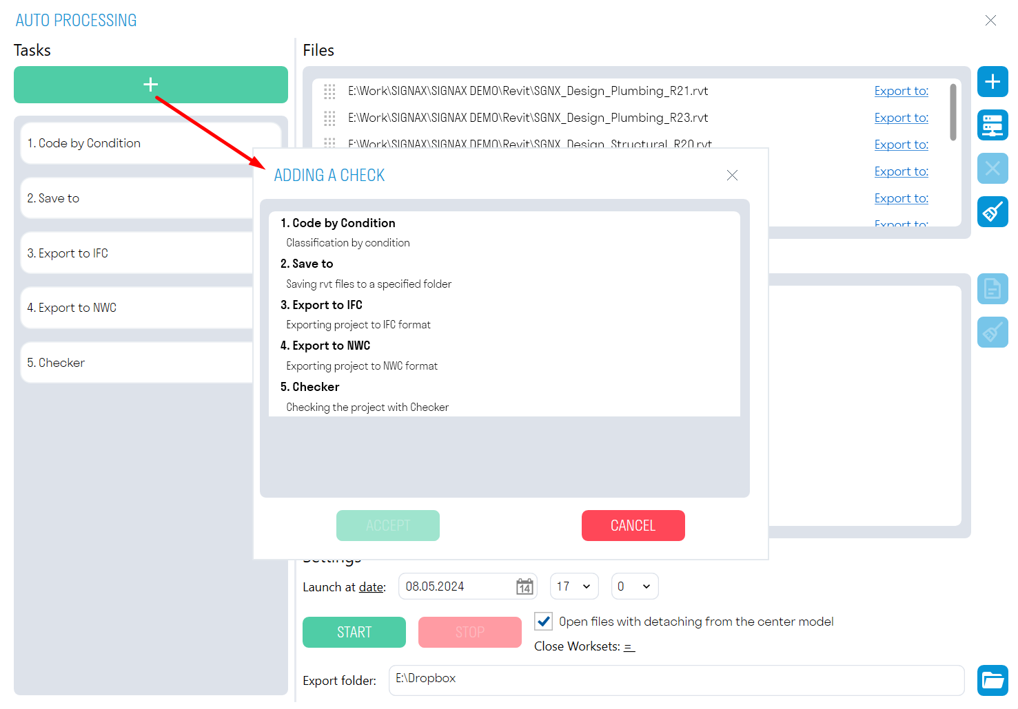
You can change the playback order of the tasks by dragging them.
- “Code by condition” assigns a classifier code to all elements based on specified conditions. The rules are taken from the file from which AutoProcessing is launched.
Note: This task must be used with the "Open files detached from central model" option disabled. Otherwise, all changes will not be saved in the source file.
- “Checker” checks the selected models for the presence of parameters in the elements and the completion of values for these parameters. The results of the check are Excel files with the check results. The check rules are taken from the file from which AutoProcessing is launched. In the "Checker" tool, you must check the boxes next to the checks to be performed.
- “Save in” saves the selected files in RVT format to the specified directory. For saving collaborative models, it is recommended to use the “Open files detached from the central model” option.
- “Export to NWC” exports the selected models in NWC format to the specified directory, using the current export settings. Export is performed from the “Navisworks” view. If the file does not contain the Navisworks view, then export is performed from the first available view containing the word “Navisworks”, for example, “BIM_Navisworks” or “Navisworks KR”. If there are no suitable views in the file, then the entire model is exported.
- “Export to IFC” exports the selected models in IFC format to the specified directory.
Note: The export directory is specified in the "Export Folder" field at the bottom of the window.
3. In the "Files" window, click

to select RVT files from your local computer, or
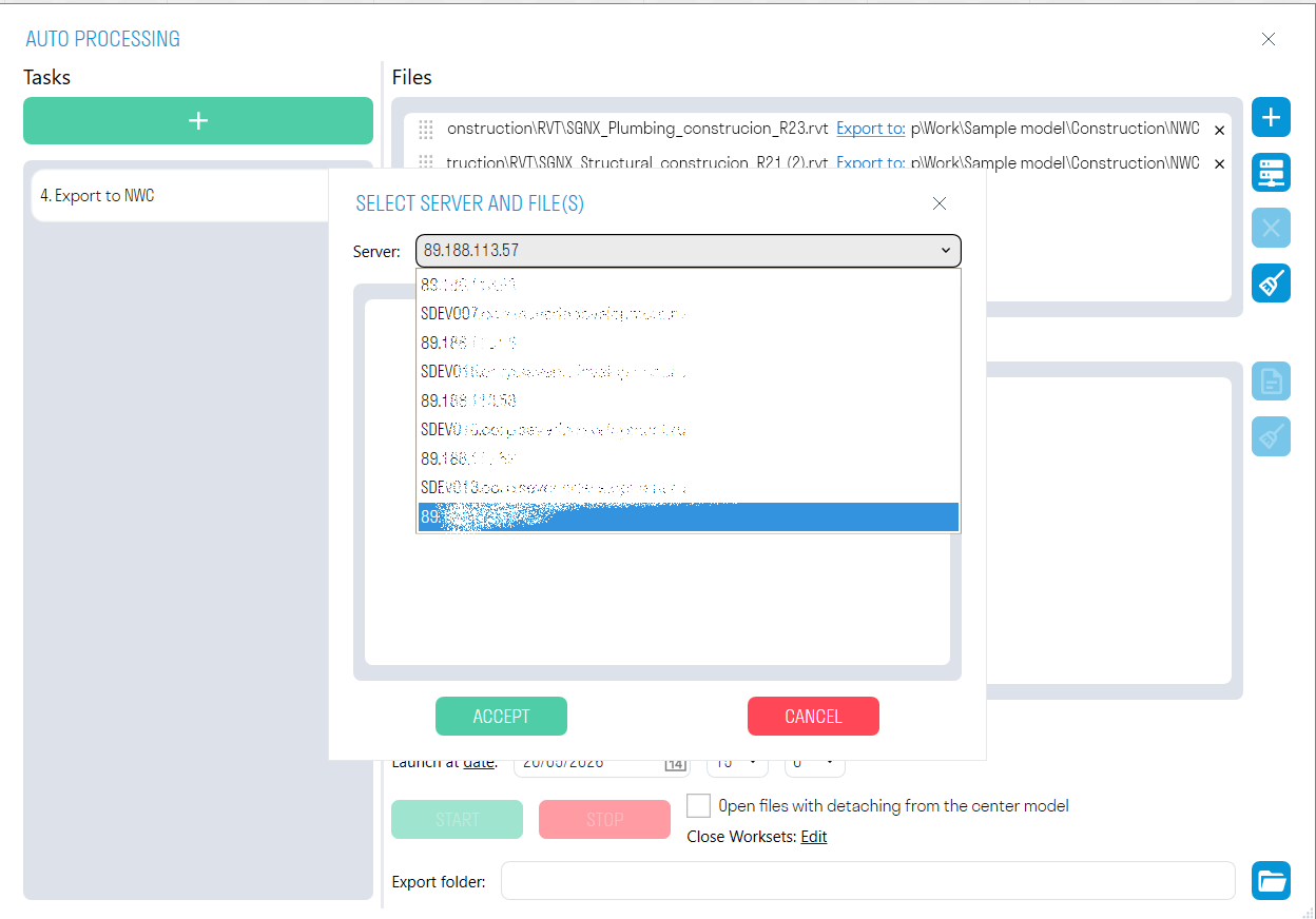
to select files from the Revit server. The previously specified tasks will be applied to the selected files.
4. The Settings window contains different options for launching AutoProcessing.
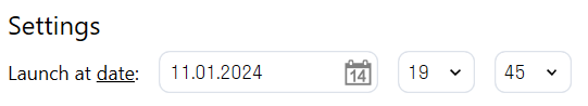
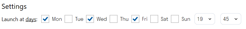
- You can choose to launch by date or by day.
For a one-time processing of a model, use the by date launch. The plugin will run once at the specified date and time.
For regular file processing, select the by day launch. The plugin will run at the same time on the specified days.
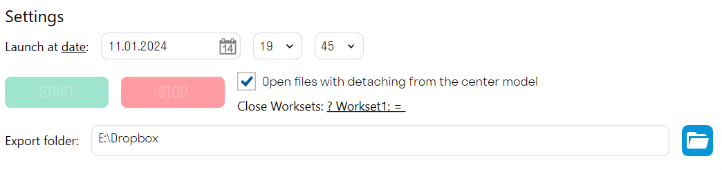
- The "Open files with detachment from central model" option allows you to open collaborative models with detachment. This is necessary when saving such models in RVT format for their subsequent transfer, for example, to a client.
Note: This option should only be used with the export commands, since changes made with the “Code by condition” command will not be saved in the source file.
-
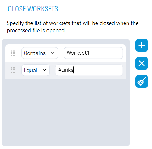
"Close workspaces" allows you to close the specified worksets when opening the file being processed. For example, you can close a workspace with linked files so that the models being processed open faster.
-
The export folder specifies the directory for exporting files.

5. After setting the launch, click "START". At the specified time, the plugin will begin opening the selected models one by one and performing the specified tasks on them. Do not close the tool or turn off the computer until the Auto-Processing process is complete.

You can monitor the plugin's operation in the "Log" window. All results of the performed actions, as well as errors that occurred during the Auto-Processing process, will be recorded here. The results can be opened in .txt format by clicking

and saved to your local computer.
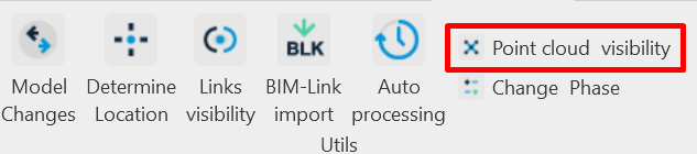
This tool allows you to enable or disable the display of point clouds in the current view. For convenience, you can bind the tool to a hotkey.
1. Click Utilities ➤ Point Cloud Visibility
This tool helps BIM professionals automate the process of uploading and checking Revit models located both on the local computer and on the Revit server. The plugin can be configured to run tasks according to preset scripts. At the specified date and time, the plugin will automatically execute the task scripts for each selected Revit file. From simply opening and checking file data, to automatically slicing apartments by parameters and exporting to NWC and IFC.
To call the utility, click in the SIGNAX PRO tab in the Utilities category “Server processing”

Then the utility window will open:
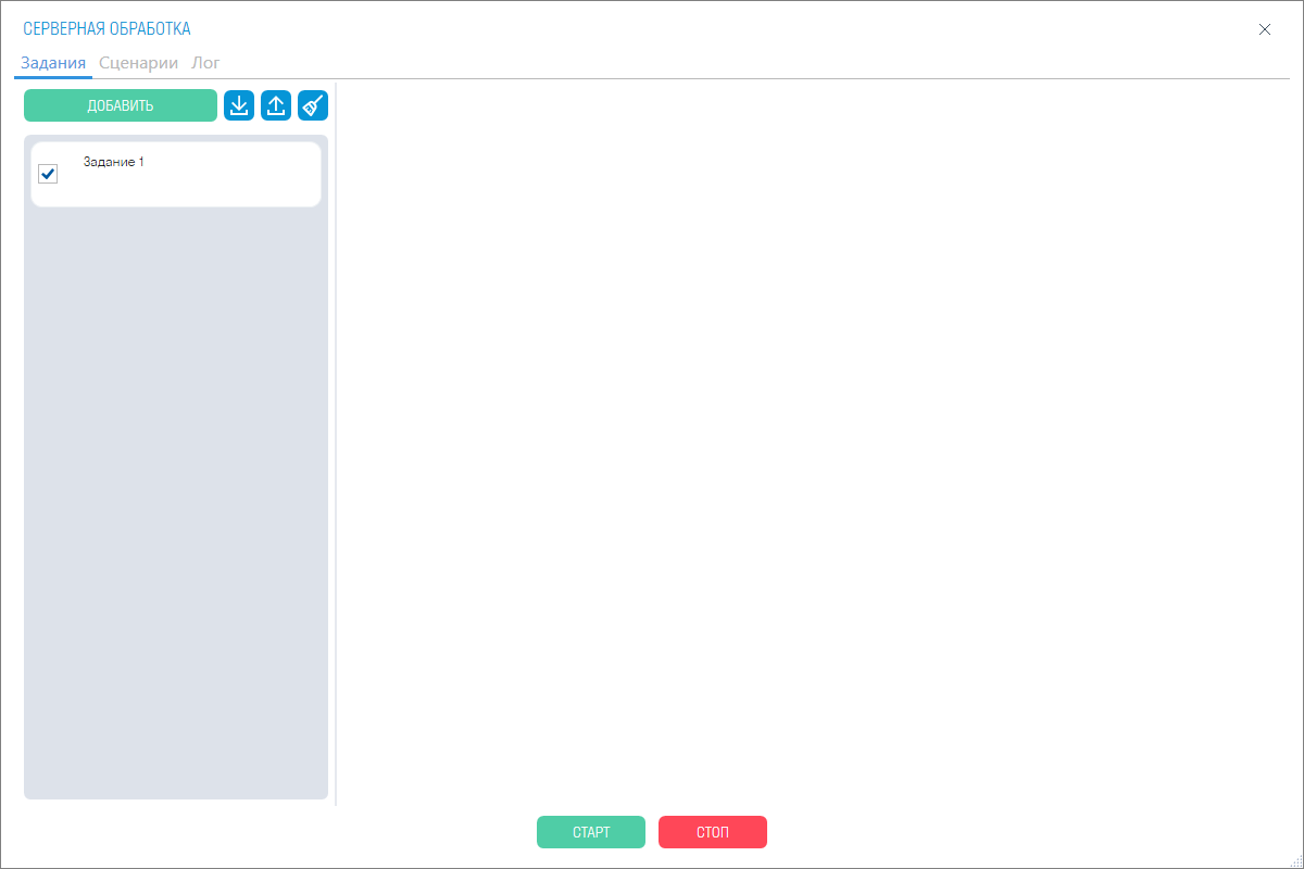
¶ The “Tasks” tab
is a window where you can add tasks for processing. These tasks can also be exported to XML files and ready-made ones can be imported.
In the Files window, click

to select RVT files from your local computer, or

to select files from the Revit server. The previously specified tasks will be applied to the selected files.
You can change the playback order of the tasks by dragging them.
You can select to run by date or day.
For a one-time processing of the model, use the by date run. The plugin will run once at the specified date and time.

To process files regularly, select by day. The plugin will run on the specified days at the same time.

You can save the report locally to the specified path or upload the report to a DOCS project by specifying the project and folder.

File processing in Tasks is based on scenarios; they are assigned to files via the drop-down list.

¶ The "Scenarios" tab
is a window similar to the "Tasks" tab. In it, you can create, export, and import action scenarios that will be followed by previously created tasks.

A scenario must have tasks. Each scenario automatically has three main tasks: "Check", "Collect information", "Open and save". You can also add 8 ready-made tasks by clicking the "Add" button.
¶ Opening and saving

1. Opening a file. Opens the project being processed either by disconnecting from cloud storage, that is, locally. Or without disconnecting from the server.
You can also set whether or not to save working spaces when opening. Also specify a list of working spaces that will be closed when reading the file being processed.
2. Closing a file. This function allows you to choose the action when closing the file being processed: you can close it and save it in the path where the file was originally opened; do not save the file; or “close and save as”.
“Close with save as” expands the saving options:
3. Save to folder. Saves the file to the specified path when closing the project.
4. Save to DOCS. Saves the file to the specified project and folder in DOCS. You can also configure the processing of models in Autodesk Forge and Tangl Viewer for further work in DOCS
5. Add date. Adds the current date to the file name when saving to the path.
6. Add to folder with date. Adds a folder with the date in the name, the folder contains the saved file.
7. Load into Tangl. Allows you to load a saved file into the Tangl Value and Tangl Control modules. Learn more about loading and integrating this solution here
Adding checks includes 8 task categories:
¶ 1. Number of Elements
This task counts the number of model elements in the report. In the task, you can specify whether to take into account rooms and spaces in the model.
¶ 2. Sheets in File
This task collects information and counts the sheets in the file. You can include sheets only with placed views, and parameterize selected sheets.
¶ 3. Revit Warnings
This task collects warnings in the project, by each type. You can also create filters that can skip specific warnings.
¶ 4. Collect Volumes by Elements
This task collects the volume of elements based on the specified filters. You can also change the quantity indicators.
¶ 5. Collect Volumes by Rooms
This task collects the volumes of rooms based on the specified filters. You can also change the quantity indicator.
¶ 6. Export
adds export to the NWC and IFC formats to the script.
NWC exports the selected models in NWC format to the specified directory, using the current export settings. Export is performed from the "Navisworks" view. If the file does not contain the Navisworks view, then export is performed from the first available view containing the word "Navisworks". If there are no suitable views in the file, then the entire model is exported.
IFC exports the selected models in IFC format to the specified directory.
¶ 7. Code by Location
The
task allows you to set a formed value for the target parameter of an element that falls inside a form-building. The value is formed from the values of the form-building parameters. A prefix and suffix can be added for each form-building parameter. The suffix has a limited length of one character and is not specified for the last parameter.
¶ 8. Apartment Slicing
The task allows you to create apartment slices based on form-building elements with parameters for the code, the code itself, prefixes, and save path. You can also export to NWC.
¶ Launch and Logs
After setting up the launch, click "START" (see 1). At the specified time, the plugin will begin opening the selected models one by one and performing the specified tasks on them. Do not close the tool or turn off the computer until the process is complete. To run the process immediately, you can click the "Run Task" button in the "Tasks" tab (see 2).

You can monitor the plugin's progress in the "Log" window. It can be viewed both in the tasks window in the “Log” tab (see 1) and in the main tabs (see 2).

The main “Log” tab will show the events of all tasks, while the log of a specific task will be shown in the window of this task.
The main “Log” window with the event log

All the results of the performed actions, as well as errors that occurred during server processing, will be recorded here. The results can be opened in .txt format by clicking on

and saved to your local computer.
The tool helps to create 3D models of apartments for their subsequent transfer to the client.
Prepare the form-generating figures in a separate file, set the parameters for the apartments, load them as a link into the main files and cut the apartments using this plugin.
¶ Preparation
¶ Creation of form-generating
In order to use the “Split by mass” utility, create a file in advance where the form-generating figures (system family: forms) used for marking apartments will be located.
In the preliminary file of form-building elements, use the link from the architecture file (or another section) as a base to mark the apartment forms. The form-building elements themselves are created through the Forms and General Plan tab by clicking the Form button in the context.

¶ Creating file
Parameter To work with the utility, you must set a parameter with apartment codes in the form-building element file. This parameter is needed to define the form-building elements themselves when working with the plugin. The apartment codes will also be entered into this parameter.
To create an apartment parameter, go to the Management section and click the Shared Parameters button.

Then, in order, create a file, create a group in it, and create a parameter in the group.
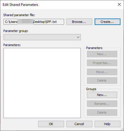
You can name the parameter whatever you like, it must be of the parameter type - text, in the case of the example parameter is called "Parameter_apartments". After creation, go to Project Parameters (the icon above from General Parameters).
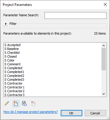
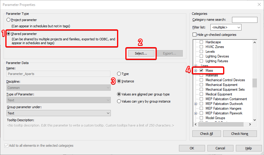
In the Project Parameters window, click the Create button. This will open the parameter properties editing window.
In the Parameter Properties window, in the Parameter Type field, select the General Parameter button and load the previously created "Parameter_apartments". You do not need to fill in anything else in the parameter data; for convenience, you can select its location in Parameter Grouping (optional). Give this parameter the Instance property and, most importantly, assign it the Forms category. Then click OK. (If successfully added, the parameter will be in the list of available ones)
After creating "Parameter_apartments" in the Forms family, it will appear in its Properties.

Enter the apartment codes you need in this parameter, for example, 1-2, 1-3, etc. This will be useful in the future for determining which apartments need to be divided.
¶ Dividing Apartments
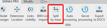
To open the utility, click "Dividing Apartments" in the SIGNAX PRO tab, Utilities category (IMPORTANT: The utility only opens in 3D view). This utility should only be called from the file you want to divide into apartments (for example: an AR, HVAC, and VK file).
After that, the utility window will open.

In the "Parameter with apartment codes" field, as mentioned earlier, we enter the prepared parameter (in the example, it is "Parameter_apartments"). This will point the plugin to the necessary form-building elements with the specified attribute.
In the "Apartment codes" field, we specify all the apartments we need, which we defined in the "Parameter_apartments" attribute. (For example: 1-1, 1-2, etc.).
In the "File prefix" field, enter any text convenient for you to name the created apartment file. By default, the program selects the name of the opened file.
The file save path is the path where future apartment files will be saved.
Export to NWC - this function allows you to export files to Navisworks format. Convenient for assembling various connections, such as AP and VK, into a single unit. (IMPORTANT: when exporting to NWC format, RVT files will not be created).
¶ Assembling apartments in Navisworks
Export to Navisworks represents multiple apartment files, different sections. Opening each one would be labor-intensive and pointless.

To assemble a complete apartment model with all sections in a single file, run the main file of the chopped apartment (for example, AP) in NWC first.

After opening the file, you can add active links of other sections via the Add button in the Home - Project tab.
After which, another section of the chopped apartment will be added to the general model.

Part of the VK and KR section separately.
The general model after adding an active link.

Thus, add all the other necessary sections, which were made using the plugin, to one general model. Save the NWC file as a separate assembly, after which the chopped apartment will be ready for publishing.
¶ Simple viewing in DOCS
When publishing an NWC file in SIGNAX DOCS, there is a "Simple viewing" function. Right-click the assembly file in DOCS and select "Share".

A selection window will open. In this window, you need to set the Publication type to Simple viewing.

A link will be available in the same window. By clicking it, the user, regardless of the presence of a license, device performance, etc., can view the finished assembly in a lighter version.

This lightweight version of the visualization offers several features:
A measurement ruler for measuring distances between objects, and selection sets for selecting both structural elements and utility networks.

This version also allows you to switch to a 2D view and use all of the above features.

This feature is useful for clients who don't have access to SIGNAX DOCS and doesn't require powerful devices. The model itself can be posted on public websites. Thus, the user can easily view the apartment and certain systems in 3D and 2D views, and take measurements if necessary.
< TOOLS FOR REVIT. Copying elements | TOOLS FOR REVIT. Acceptance >